00193732-02.pdf - 第60页
2 Retrofit Instructions for PCB Camera Multicolor, HS-50 / HS-60 SIPLACE HS- 50/HS-60 2.7 Installing PCB Camera Board and PCB Camera Multicolor 11/2004 Edition 60 Only HS-50: 2 Find ou t before ins talling the PCB ca mer…
SIPLACE HS-50/HS-60 2 Retrofit Instructions for PCB Camera Multicolor, HS-50 / HS-60
11/2004 Edition 2.7 Installing PCB Camera Board and PCB Camera Multicolor
59
: Unscrew the 3 spacer bolts on the bottom of the gantry (fork wrench/socket wrench size 6).
These bolts (L = 9 mm) are exchanged for bolts from the retrofit kit (L = 8.5 mm).
2.7.2 Installing the PCB Camera Multicolor
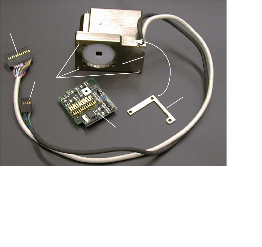
Abb. 2.7.3 PCB Camera Multicolor Assembly with Distance Plate (Spacer)
2
2
: Beginning from the bottom of the gantry, screw the 3 new spacer bolts (L = 8.5 mm) from the
retrofit kit into the camera holder (6 mm open-end / socket wrench).
2
2
2
2
1 Distance plate (Spacer)
2 PCB camera Multicolor incl. cable and connector
3 Fasteners for PCB camera Multicolor: 3 hex head cap screws M3 x 14, captive
4 "PCB camera board, modular"
5 Cable "illumination", camera *) -> Connection to X3 at "PCB (camera) board modular"
6 Cable "camera" *) -> Connection to X4 at "Vision board, modular"
2
1
3
4
5
6
2 Retrofit Instructions for PCB Camera Multicolor, HS-50 / HS-60 SIPLACE HS-50/HS-60
2.7 Installing PCB Camera Board and PCB Camera Multicolor 11/2004 Edition
60
Only HS-50: 2
Find out before installing the PCB camera Multicolor which PCB or substrate thickness will be pla-
ced. Depending on the thickness, it will or will not be necessary to place the distance plate (spa-
cer) from the retrofit kit under each camera, to be with the PCB as near as possible in the focus.2
Following the configuration of the Multicolor PCB camera at the line computer, including descri-
bing the PCB or substrate (entry of the thickness), a message can be accessed at the line com-
puter as a check (see 2.8.1). 2
In most cases, adequate imaging quality will still be achieved even it work is done outside the ran-
ges indicated above.
With the spacer plate removed, system fiducials can still be adequately recognized. 2
2
: Ascertain the PCB/substrate thickness to be processed now.
: Use the table to determine whether the distance plate is required.
If yes, place the distance plate (from the camera retrofit kit on the camera’s assembly surface
in the correct rotational position (this is determined on the basis of the holes).
2
2
2
2
2
2
2
2
2
2
2
2
2
2
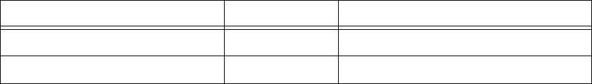
PCB or substrate thickness Focus Install distance plate (spacer)
0.3 - 3.4 mm 1.7 mm Yes
1.5 - 4.5 mm 3.2 mm No
SIPLACE HS-50/HS-60 2 Retrofit Instructions for PCB Camera Multicolor, HS-50 / HS-60
11/2004 Edition 2.7 Installing PCB Camera Board and PCB Camera Multicolor
61
HS-50 and HS-60 2
: Put the PCB camera Multicolor, eventually with distance plate, in right position upwards onto
the distance plates.
: Screw the camera with the 3 unloosable Allan screws M 3 x 14.
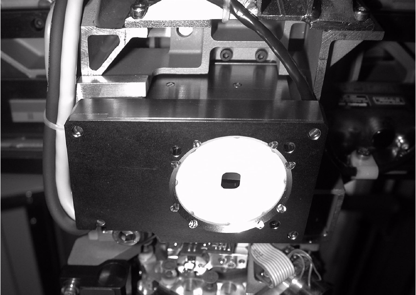
Abb. 2.7.4 Fastening the PCB Camera Multicolor (View from below, diagonally)
2
2
2
2
2
2
2
2
2
2
2