00193732-02.pdf - 第64页
2 Retrofit Instructions for PCB Camera Multicolor, HS-50 / HS-60 SIPLACE HS- 50/HS-60 2.7 Installing PCB Camera Board and PCB Camera Multicolor 11/2004 Edition 64 2.7.4 Laying Cables, Plugging into PCB Camera Board and V…
SIPLACE HS-50/HS-60 2 Retrofit Instructions for PCB Camera Multicolor, HS-50 / HS-60
11/2004 Edition 2.7 Installing PCB Camera Board and PCB Camera Multicolor
63
2.7.3 Installing the "PCB Camera Board, Modular" from the Retrofit Kit
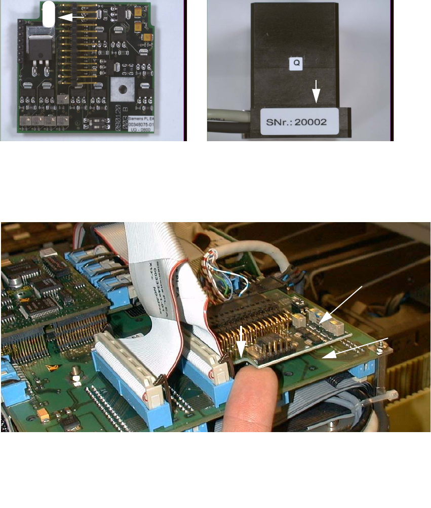
: Check the serial number of the PCB camera board, modular: It must correspond to the number
on the Multicolor PCB camera. Per gantry this allocation must be maintained during installa-
tion. The position of the number is shown in the following illustration.
Abb. 2.7.5 Check: the identical serial number on modular PCB Camera Board and PCB Camera Multicolor
: Screw the distance plates from the retrofit kit onto the "Vision board, modular".
: Plug the "PCB camera board, modular" onto the "Vision board, modular" in the correct position.
2
Abb. 2.7.6 Installing the "PCB Camera Board, Modular" from Retrofit Kit
: Screw the PCB camera board, modular.
1 Head PCB HS-50 assembly (modular)
2 PCB camera board, modular, manufacturer = Sticksel
3 Position of the recess
20002
3
2
1
2 Retrofit Instructions for PCB Camera Multicolor, HS-50 / HS-60 SIPLACE HS-50/HS-60
2.7 Installing PCB Camera Board and PCB Camera Multicolor 11/2004 Edition
64
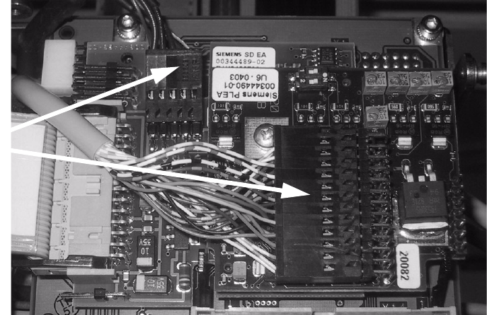
2.7.4 Laying Cables, Plugging into PCB Camera Board and Vision Board
: Run the two cables from the PCB camera Multicolor up to the head PCBs.
: Plug the connectors of the PCB camera Multicolor into the "Vision board modular" and into the
"PCB camera, modular" located above it.
2
2
: Fasten the cables running upward such that the strain on the connectors is relieved.
: Fasten the flat ribbon cables.
2
2
2
2
2
2
2
2
2
Plug the
camera cable
SIPLACE HS-50/HS-60 2 Retrofit Instructions for PCB Camera Multicolor, HS-50 / HS-60
11/2004 Edition 2.8 Configuration PCB Camera Multicolor on LC
65
2.7.5 Assembling the Placement Head and the Machine
: Place the covers previously removed back on the placement heads and screw them.
: Place the covers on to cable pits.
: Re-install the servo unit (socket hex head cap screw M5).
: Apply screw-locking compound to the screw.
: Remove all of the tools, etc., from the machine’s working area.
: Before docking the movable component changeover table, push the gantry until it is over the
PCB conveyor area.
: Place the side panel of the machine frame and secure it (with a total of 6 screws).
: Install the head crash protections over the component changeover tables.
: Dock all movable component changeover tables with the previous allocation.
: Lock the doors of the machine frame.
: Close the safety doors and safety hoods.
: Turn the machine on at the main switch. The compressed air must be on.
: Resume the work with the configuration at the line computer.
2.8 Configuration PCB Camera Multicolor on LC
The software version 502.01 or later is a prerequisite for using the PCB camera Multicolor. 2
The optional PCB camera Multicolor is selected in the station configurator of the UNIX line com-
puter (LC). Insofar as this operation is concerned it can occur before or after the PCB camera Mul-
ticolor is selected at the station in question, in the SITEST program 502.xx. 2
2
: In the menu bar at the top, select "Services".
: In the pull-down menu that opens, select the option:
"Station configuration".
: The window from which the machine is selected opens:
Select the machine on which the optional PCB camera Multicolor was installed.
2
2
2