00193732-02.pdf - 第67页
SIPLACE HS-50/HS-60 2 Retrofit Instructions for PCB Camera Mult icolor, HS-50 / HS-60 11/2004 Edition 2.8 Configuration PCB C amera Multicolor o n LC 67 : In the "Data manag er" window s elect the field "O…
2 Retrofit Instructions for PCB Camera Multicolor, HS-50 / HS-60 SIPLACE HS-50/HS-60
2.8 Configuration PCB Camera Multicolor on LC 11/2004 Edition
66
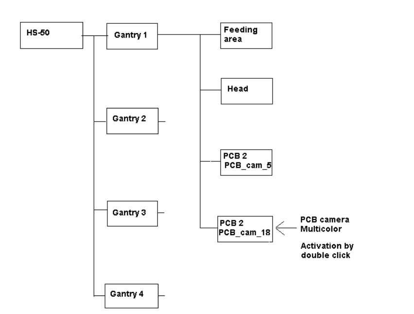
: The "Main view of "Structure editor" is displayed automatically.
As shown afterwards, the selected machine is displayed graphically, arranged by gantries, and
with the pertinent substructures (component feeding areas, placement heads, PCB cameras,
options, etc.).
Abb. 2.8.1 Structural Overview
: The field "PCB camera Multicolor" is deactivated. Activate the optional PCB camera Multicolor
with a double click on "LP PC_cam _18", as illustrated above.
: Do this for all 4 gantries.
: In the menu bar at top, in the Station Editor, select "File" -> "Save" - END".
: Then select: "File" -> "Data manager".
: Double click on the ICONs for "Master data".
: In the window that opens, double click on "Stations".
: Click once on the "Double click" field that opens and click once on "Compiler" to select it.
: Select with a double click the pertinent station at which the PCB camera Multicolor is used /
was retrofitted.
SIPLACE HS-50/HS-60 2 Retrofit Instructions for PCB Camera Multicolor, HS-50 / HS-60
11/2004 Edition 2.8 Configuration PCB Camera Multicolor on LC
67
: In the "Data manager" window select the field "OK".
All of the windows are closed.
This concludes the work on the line computer for the configuration of the PCB camera Multi-
color.
: If you have not done so already, carry out the check "Camera Focus.... Substrate thickness"
as described in Abschn. 2.8.1. After this step continue with the activation/ configuration and the
illumination check (see Abschn. 2.9).
2.8.1 Camera Focus, dependent on PCB/Substrate Thickness
The focus level for the current substrate or PCB thickness can be optimized by installing or remo-
ving the distance plate (spacer) between the Multicolor PCB camera and camera holder. 2
The decision as to whether or not to work with the distance plate can be made during the course
of the retrofitting on the basis of the table (see Abschn. 2.7.2). As a final check, a specification can
be accessed at the line computer as described below: 2
After describing the PCB, including entering the PCB/substrate thickness (= height) in the cluster
editor, conducting the produceability check and specifying the job for the relevant station in the job
editor you can check under -> Services -> Error messages.
If a change must be made involving the distance plate (spacer), a message such as the following
one is displayed:
2
Warning: PCB xxx.la is more than 3.400 mm thick (x.y > 3.400 mm)
For this reason, camera 18 must be mounted without the spacer.
or
Warning: PCB xxx.la is less than 1.500 mm thick (x.y < 1.500 mm).
For this reason, camera 18 must be mounted with the spacer.
xxx.la = name of PCB
x.y = in the cluster editor entered thickness (height) of the PCB / substrate
Camera 18 = PCB camera Multicolor
: Continue with the activation / configuration and the illumination check (see 2.9).
2 Retrofit Instructions for PCB Camera Multicolor, HS-50 / HS-60 SIPLACE HS-50/HS-60
2.9 SITEST: Configuration and Illumination Check of all PCB Cameras Multicolor 11/2004 Edition
68
2.9 SITEST: Configuration and Illumination Check of
all PCB Cameras Multicolor
The configuration of the PCB Camera Multicolor can be performed before or after the configura-
tion in the station configurator of the UNIX line computer. 2
DANGER
Pay attention to the DANGER text regarding work with the SITEST program in Section 2.2. 2
The requirement for the configuration is that the 4 PCB cameras Multicolor are retrofitted and the
safety hoods and safety doors are closed.
All component changeover tables must be moved into the machined and docked. 2
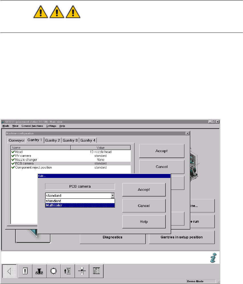
: Change over into the SITEST program.
: Select "Settings" -> "Machine configuration".
: Select: "Gantry 1" -> "PCB camera" -> "Edit" (button). The "Edit" window is displayed:
Fig. 2.90.1 "Edit" Window: Selecting the PCB Camera Multicolor