00193732-02.pdf - 第71页
SIPLACE HS-50/HS-60 2 Retrofit Instructions for PCB Camera Mult icolor, HS-50 / HS-60 11/2004 Edition 2.9 SITEST: Con figuration and Illumination Check of all PCB Cameras Multicolor 71 : The screen "Illumi nation va…
2 Retrofit Instructions for PCB Camera Multicolor, HS-50 / HS-60 SIPLACE HS-50/HS-60
2.9 SITEST: Configuration and Illumination Check of all PCB Cameras Multicolor 11/2004 Edition
70
2
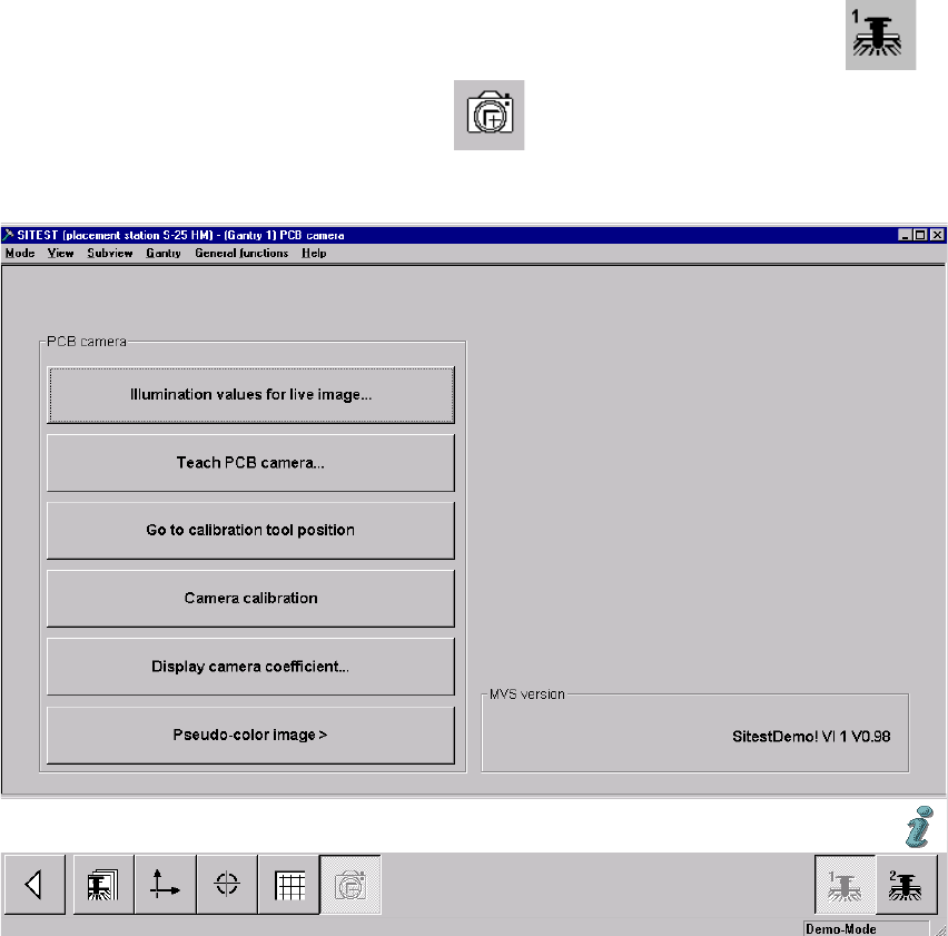
: In the SITEST program 502.xx select the ICON "Gantries" and then the "Gantry 1" .
: Click on the CON "PCB camera functions" .
The following screen is displayed (using S-25 HM as an example):
Fig. 2.91.2 Menu "Setting of Illumination" for PCB Camera"
2
: Click on the button "Illumination values for live image".
In principle, you can use this function to test whether the illumination of the PCB camera Mul-
ticolor is activated. The illumination levels "White" and "Blue" are visible; "IR" is not.
2
2
2
2
2
2
SIPLACE HS-50/HS-60 2 Retrofit Instructions for PCB Camera Multicolor, HS-50 / HS-60
11/2004 Edition 2.9 SITEST: Configuration and Illumination Check of all PCB Cameras Multicolor
71
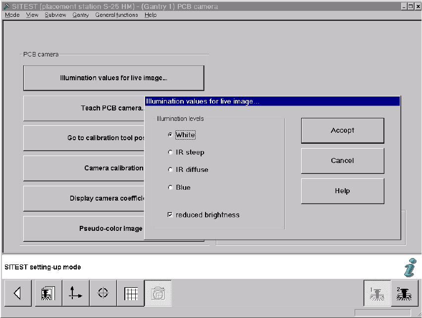
: The screen "Illumination values for live image" is displayed (using S-25 HM as an example):
Fig. 2.91.3 Screen: "Illumination Values for Live Image"
: Test at least the illumination levels "White" and "Blue" because their light is visible.
: Click on the "Radio button" to select the illumination level "White".
: Deactivate the button "Reduced brightness" and click on the button "Accept".
The complete illumination level is therefore activated at the outset.
: Switch to the menu "Teach PCB camera" -> Click on the button "PCB camera":
Make a visual check (with safety hoods closed):
The camera’s white light must flash.
: Once again, press the button "Illumination values for live image".
: Now activate the option "Reduce illumination".
This reduces the illumination level by one-half.
: Click on the button "Accept" again.
: Make a visual check (with the safety hoods closed):
The camera’s white light must flash repeatedly but not as brightly as before.
: Execute the above-described check for illumination level "blue" as well.

2 Retrofit Instructions for PCB Camera Multicolor, HS-50 / HS-60 SIPLACE HS-50/HS-60
2.92 Safety Check: Shutdown of Illumination 11/2004 Edition
72
: Exit the menu "(Gantry 1) PCB camera".
: In the menu "PCB functions" select the button "PCB camera" of gantry 2 or 3 or 4
Perform the above-described operation for these PCB cameras Multicolor.
NOTE:
If you would like to check the IR illumination levels too, perform the above-described operation in
a like manner for these levels also and. Place a white sheet of paper under the camera. As a
check, switch over to the vision screen in each case. 2
: Afterward, test to make certain that the camera illumination goes OFF in response to safety
shutoff:
2.92 Safety Check: Shutdown of Illumination
: Activate again - as described above - visible camera illumination at each gantry and, while the
light is starting to flash ON, open a safety hood or a cover (PCB input / PCB output):
: Check: The light must turn OFF when this occurs. This results from the interruption of the cur-
rent from the voltage regulator module (50 V) by the retrofitted safety relay.
: If an error occurs, check and correct the wiring on the basis of the circuit diagrams.
: Repeat this procedure with the key-operated switch in the normal position and in the service
position. The vision screen must remain dark!
: Continue with the illumination setting.