00193732-02.pdf - 第75页
SIPLACE HS-50/HS-60 2 Retrofit Instructions for PCB Camera Mult icolor, HS-50 / HS-60 11/2004 Edition 2.93 Illumination Setting 75 : Se lect the I CON "S etting il luminati on" : In the "illu mination"…

2 Retrofit Instructions for PCB Camera Multicolor, HS-50 / HS-60 SIPLACE HS-50/HS-60
2.93 Illumination Setting 11/2004 Edition
74
2.93.2 Orientation Aid for Selecting Illumination
The following table is derived from empirical values and is therefore only to serve as an orientation
aid. A few materials often exhibit very drastic fluctuations (particularly in the case of CEM1), the-
refore the best illumination has to be ascertained through testing. In each instance this is done by
selecting the setting for illumination during the course of a sample placement with recognition of
the position of the pertinent PCBs or ceramic substrates. 2
2.93.3 Setting the Illumination
The best illumination selection must be ascertained by using the function "Test fiducials" or the
substrate to be populated. 2
NOTE:
The processes which must be executed prior to setting the illumination are described in detail in
the section "Teaching Fiducials" or "Teaching Synthetic Fiducials" of the User Manual, Software
version SR 502.xx.
During them, the current substrate or PCB is moved onto the processing belt of the conveyor and
mechanically centered / clamped in place. 2
2
2
2
2
2
Base material Fiducial material Oblique illu-
mination
BLUE
Infrared
light
White light
FR 4 Tin x
Ceramic NiAu, Cu, AgPl x
Ceramic AgPt x
CEM1 Bright copper fiducials,
tin
x
CEM1 Fiducials covered by sol-
der resist
(x) x
Flex on alumi-
num carrier
x
SIPLACE HS-50/HS-60 2 Retrofit Instructions for PCB Camera Multicolor, HS-50 / HS-60
11/2004 Edition 2.93 Illumination Setting
75
: Select the ICON "Setting illumination"
: In the "illumination" menu select the "Setting illumination" button.
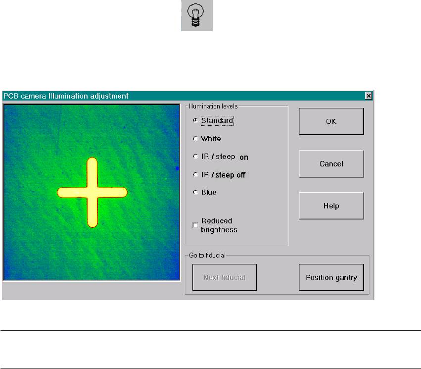
The following screen will appear:
Fig. 2.13.1 Screen: "Setting the Illumination"
NOTE:
Utilize Abschn. 2.12.2 and the table in Abschn. 2.12.3 to select the best type of illumination. 2
: Select the desired illumination level by activating the pertinent radio button.
: Select complete or reduced brightness by activating or deactivating the rectangular field.
: Select the button "Positioning the gantry" and position the gantry over the fiducial that is cur-
rently to be recognized / tested.
: Check the quality of the image on the vision screen (see the section "Teaching Fiducials" in the
User Manual).
: If the image of the fiducial is still not optimal, select another illumination level or, if appropriate,
change the brightness too and select the button "Positioning the gantry" again.
: If the image of the fiducial is alright, select the button "OK".
As a result, the illumination set is accepted for all 4 gantries.
2
2
2
2 Retrofit Instructions for PCB Camera Multicolor, HS-50 / HS-60 SIPLACE HS-50/HS-60
2.14 Attachments: PCBs, Cables and Circuit Diagrams 11/2004 Edition
76
2.14 Attachments: PCBs, Cables and Circuit Diagrams
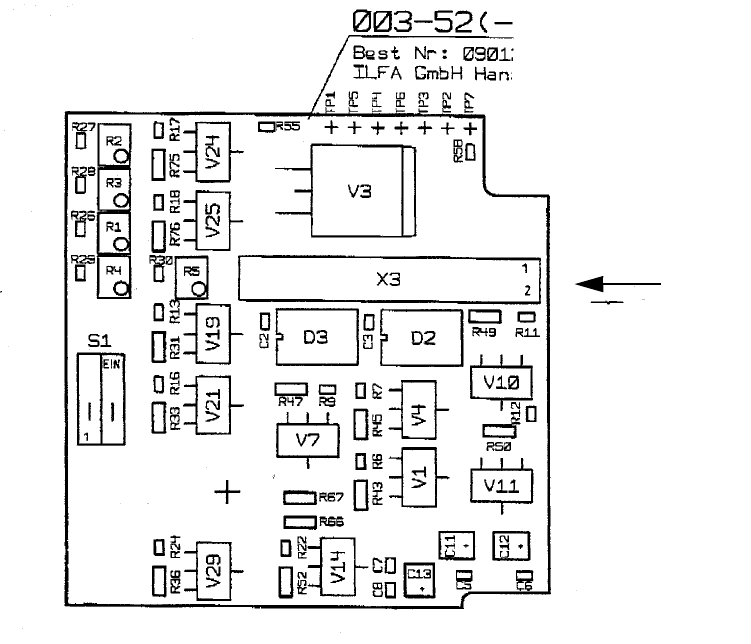
2.14.1 Layout: PCB Camera Board and Vision Board, Modular, HS-50
2
Fig. 2.14.1 Layout: PCB Camera Board, Modular, HS-50 and S-25 HM, Made by Sticksel
PCB Camera
Multicolor" -> X3
Cable
"Illumination of the
Layout, component side