M7_ServiceManual_e.pdf - 第20页
1 Installation 1-12 B B A A M7-3S Bottom face of Jack-up Points A . Bottom face of Jack-up points B . NOTE: The hydraulic jacks m ust satisfy the foll owing requirement s. Allowable load: 1.5 tons or hi gher Hook size: 1…
1 Installation
1-11
C
A B
D
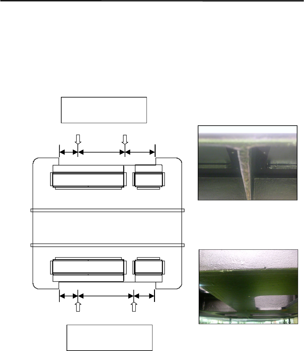
Jack-up Point
The four Jack-up points are determined considering the structure of M7 base face and balance ratio.
M7-3L, M7-2L
Bottom face of Jack-up Points; ACD.
Bottom face of Jack-up Point B.
250 (500) 250
330
(
810
)
400
330
(
730
)
480
Front Side
Jack-up point
Two each at front and rear
Rear Side
Jack-up point
Two each at front and rear
1 Installation
1-12
B
B
A A
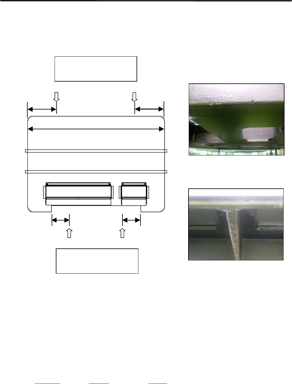
M7-3S
Bottom face of Jack-up Points A.
Bottom face of Jack-up points B.
NOTE: The hydraulic jacks must satisfy the following requirements.
Allowable load: 1.5 tons or higher
Hook size: 100mm or more (stroke)
Part Name
Part No. Remark
PLATE,BASE LG0-M8911-00X For plates 1 and 2
GOM,BASE LG0-M8912-00X Base rubber
190 190
310
310
Front Side
Rear Side
19300
Jack-up point
Two each at front and rear
Jack-up point
Two each at front and rear
1 Installation
1-13
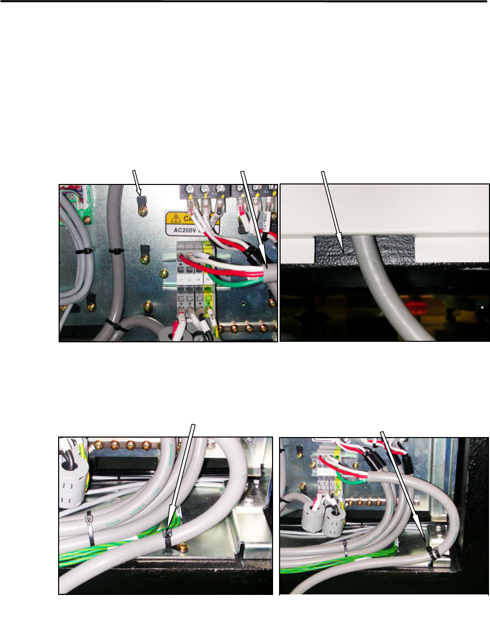
Power Cable Wiring
Route the power cable to outside the mounter through the rectangle cable hole at the lower part of the rear
cover. (See Fig. 1 and 2.)
The power cable should be secured inside the mounter to prevent accidental disconnection by pulling on the
cable outside the mounter.
To fasten the power cable with cable ties, first attach cable clamps to unused screw holes then insert cable
ties through the cable clamps. Or bind the power cable to the terminal-panel leg with cable tie. (See Fig.3
and 4.)
Recommended cable: 3.5mm
2
, withstanding voltage 600V (VCT or equivalent)
Cable stripping length: 12mm length
Cable clamp Power cable Cable hole at the bottom of the rear cover
Fig.1
Fig.2
Fasten the power cable using a cable
clamp and a cable tie.
Fig.3
Fig.4
Bind the power cable to the
terminal-board leg with cable ties.