M7_ServiceManual_e.pdf - 第22页
1 Installation 1-14 Removal of Rust Inhibiting Grease At packing and shipping, a large amount of grease is applied on the surface of each ball-screw and linear guides on Y-axis in order to prevent rust. As each axis move…
1 Installation
1-13
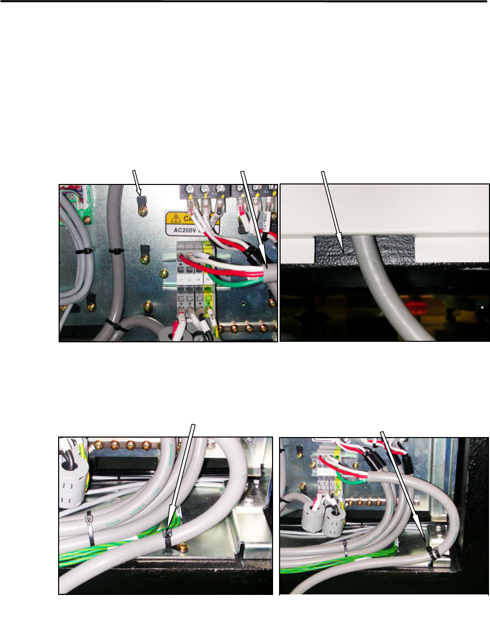
Power Cable Wiring
Route the power cable to outside the mounter through the rectangle cable hole at the lower part of the rear
cover. (See Fig. 1 and 2.)
The power cable should be secured inside the mounter to prevent accidental disconnection by pulling on the
cable outside the mounter.
To fasten the power cable with cable ties, first attach cable clamps to unused screw holes then insert cable
ties through the cable clamps. Or bind the power cable to the terminal-panel leg with cable tie. (See Fig.3
and 4.)
Recommended cable: 3.5mm
2
, withstanding voltage 600V (VCT or equivalent)
Cable stripping length: 12mm length
Cable clamp Power cable Cable hole at the bottom of the rear cover
Fig.1
Fig.2
Fasten the power cable using a cable
clamp and a cable tie.
Fig.3
Fig.4
Bind the power cable to the
terminal-board leg with cable ties.

1 Installation
1-14
Removal of Rust Inhibiting Grease
At packing and shipping, a large amount of grease is applied on the surface of each ball-screw and linear
guides on Y-axis in order to prevent rust. As each axis moves an excess grease is gradually removed from
their surface and a proper amount of grease remains as a lubricant.
For this reason, when these axes are moved at installation, the extra grease may be built up on ball-screw
nuts, on linear guide sliders, and both ends of each axis. If you run the mounter at high speed (production)
without wiping it away, the grease may be scattered around due to centrifugal force and vibration, and that
may stick to cameras, sensors, or a board.
Please perform a warm-up at low speed once the origin is acquired after installation, and wipe off any
excess grease as necessary.
The mounter may not function properly when grease sticks to the sensors
and the cameras.
ACTION:
① Check and remove any board and tools from inside of the mounter, and then perform origin
acquisition.
② Select Main Menu> Manual> Warm Up.
③ Select Warm-up & Self-diagnostics> Setting.
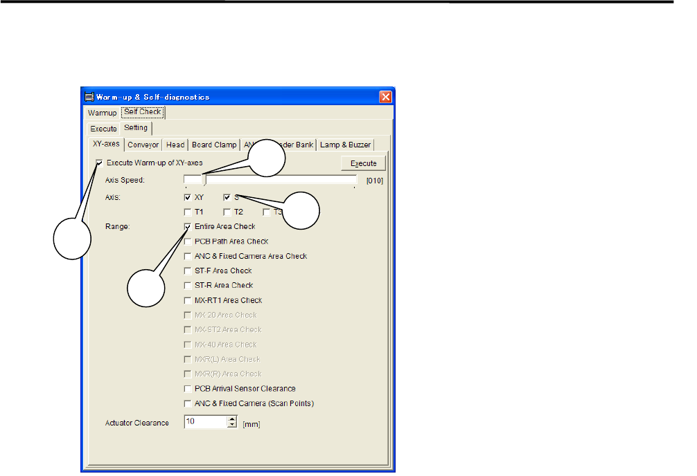
④ Select [XY-axes] and set up the parameters as follows.
1 Installation
1-15
***** This function is not ready for now. *****
⑤ Uncheck all the items other than the [XY-axes] tab. Uncheck all the items in [Conveyer], [Head],
[Board Clamp], [ANS], [Feeder Bank], and [Lamp & Buzzer] tabs (tabs may vary due to mounter’s
option ) in order to carry out only the selected items in the [XY-axes] tab.
⑥ Select the upper [Execute] tab and click <Ageing>.
When [Execute] tab is selected, the <Execute> button and the<Ageing> button are Shown at the
bottom of the window. Click <Ageing>.Clicking the <Execute> button enables to perform warm-up
only a single cycle and sufficient ageing is not carried out.
1: Check the “Execute Warm-up of
XY-axes” box.
2: Move the scroll bar and set
“Axis Speed” at 10%.
3: Check the “XY” box for the item
“Axis”.
4: Check the “Entire Area Check“ box
for the item “Range”.
NOTE: It is not necessary to check
box for the other items.
3
1
2
4