M7_ServiceManual_e.pdf - 第24页
1 Installation 1-16 ⑦ Continue ageing for 5 to 10 m inutes. After 5 to 10 minutes, cl ick the <Stop> button t o stop ageing. ⑧ Wipe off excess grease. Use a unwoven cloth to wip e off excess grease which is built u…
1 Installation
1-15
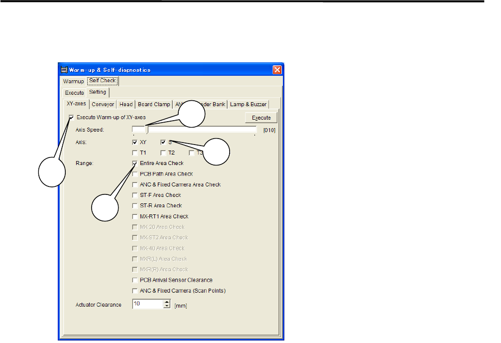
***** This function is not ready for now. *****
⑤ Uncheck all the items other than the [XY-axes] tab. Uncheck all the items in [Conveyer], [Head],
[Board Clamp], [ANS], [Feeder Bank], and [Lamp & Buzzer] tabs (tabs may vary due to mounter’s
option ) in order to carry out only the selected items in the [XY-axes] tab.
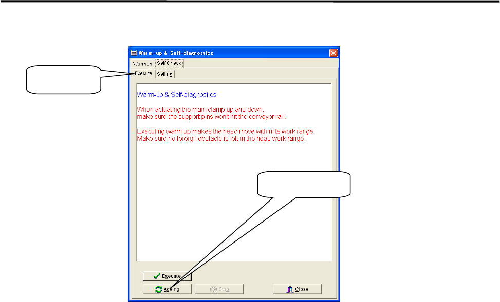
⑥ Select the upper [Execute] tab and click <Ageing>.
When [Execute] tab is selected, the <Execute> button and the<Ageing> button are Shown at the
bottom of the window. Click <Ageing>.Clicking the <Execute> button enables to perform warm-up
only a single cycle and sufficient ageing is not carried out.
1: Check the “Execute Warm-up of
XY-axes” box.
2: Move the scroll bar and set
“Axis Speed” at 10%.
3: Check the “XY” box for the item
“Axis”.
4: Check the “Entire Area Check“ box
for the item “Range”.
NOTE: It is not necessary to check
box for the other items.
3
1
2
4
1 Installation
1-16
⑦ Continue ageing for 5 to 10 minutes.
After 5 to 10 minutes, click the <Stop> button to stop ageing.
⑧ Wipe off excess grease.
Use a unwoven cloth to wipe off excess grease which is built up on ball-screw nuts, on linear guide
sliders, and both ends of each axis.
NOTE: Refer to Chapter 3 Mechanical Section for the location of each axis.
⑨ Check to be sure that the excess grease has not been scattered around.
Make sure the excess grease has not been stuck on sensors, cameras, conveyer and its belts, and ANC
When it has been stuck on these parts, remove it with unwoven cloth.
NOTE: Refer to Chapter 3 mechanical Section for more detail in cleaning of scan camera and mirror.
Ageing Button
Execute Tab
1 Installation
1-17
Pre-Process and Post-Process of The Mounter
Connecting Pre-Process and Post-Process
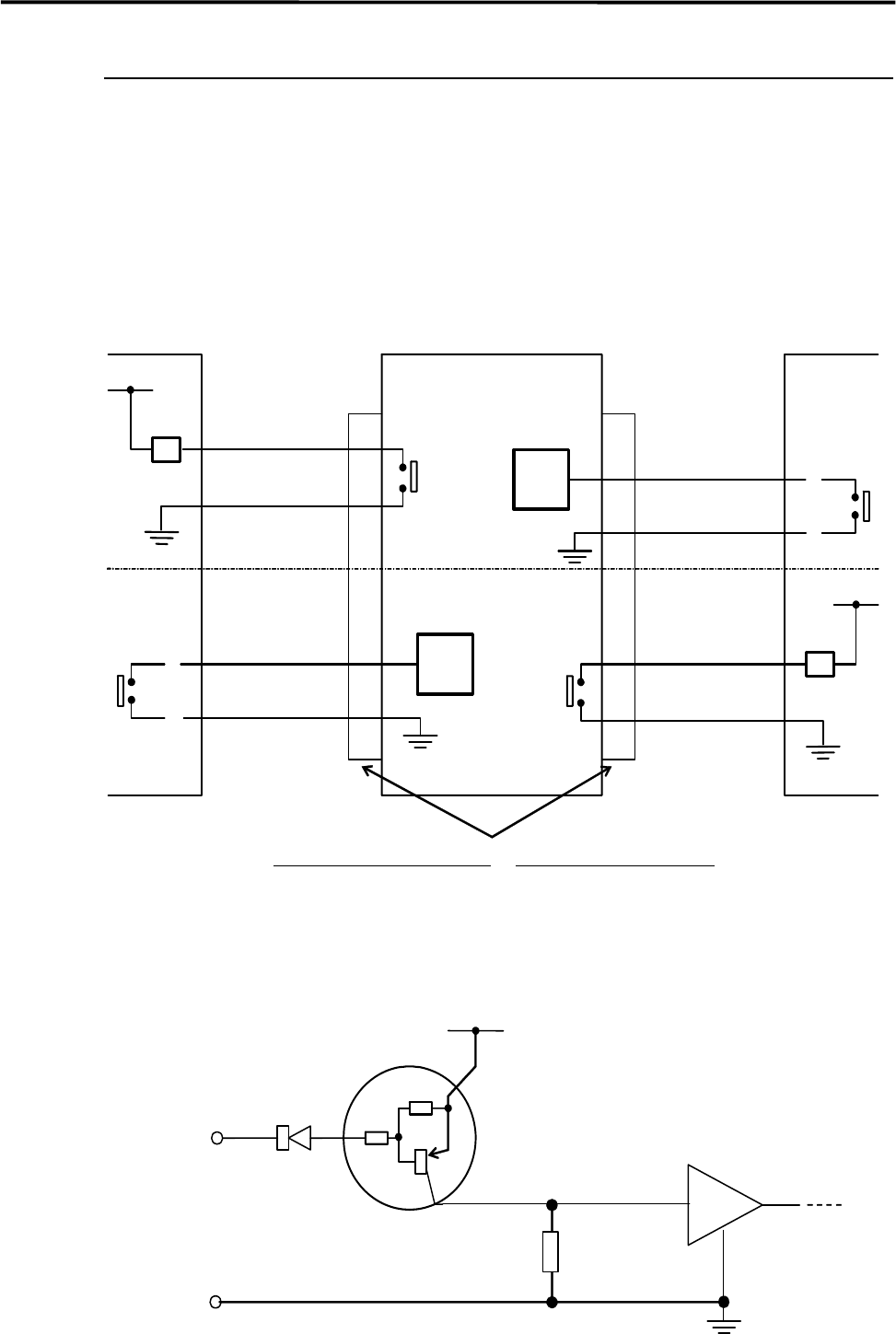
When using other manufacturer’s machines as the pre-process or post-process, connect them as shown in
the below diagram. No-voltage output (relay) is recommended for post-process.
Standard spec. : Upper half of the diagram.
SMEMA Interface spec. : Whole diagram.
*INPUT
CIRCUIT
*INPUT
CIRCUIT
2
1
CN2 CN1
Post-process
Connector (Cable side)
AMP
206044-1(plug)
66099-2 or equivalent (pin)
206070-1(cable clamp)
Connector (Mounter side)
AMP
206043-1(receptacle)
Mounter Pre-process
BOARD
AVAILABLE
BOARD
AVAILABLE
MACHINE
NOT READY
4.7KΩ
4.7KΩ
Input
terminal
*INPUT CIRCUIT
+5V
30VDC 1A or less
100VAC 0.5A or less
RELAY
RELAY
MACHINE
NOT READY
3
4
2
1
3
4
COM