AX501最新3.6x版英文操作手册 - 第14页
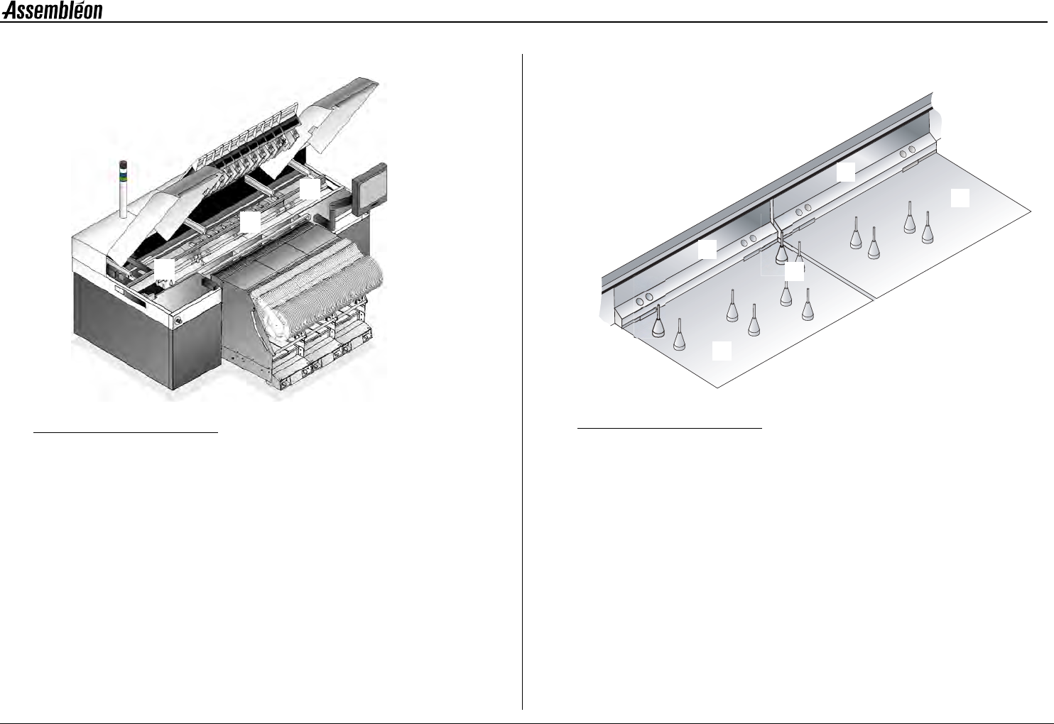
4022 593 51894 Operatin g Man ual 09.01 AX-301/501, AX-3/5 14 2 2.3 T r ansport module Figure 10 Transport module The tr ansport m odule m oves th e boards thr ough the machin e. 1R u n - i n . 2W o r k a r e a . 3R u n …
4022 593 51894 Operating Manual
09.01 AX-301/501, AX-3/5 13
2
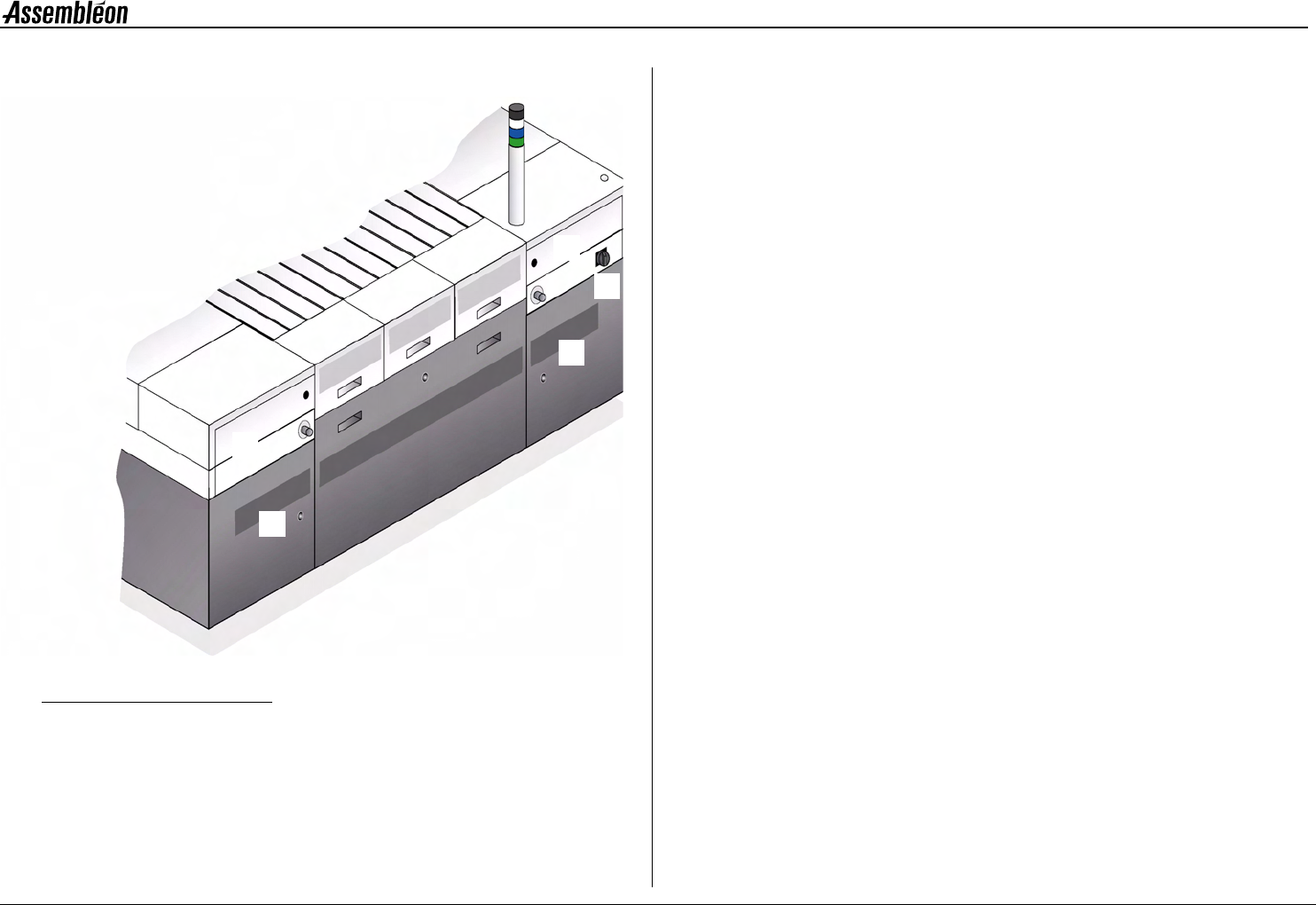
2.2 Rear side items
Figure 9 Rear side items
1 Electrical main switch.
2 Rear-left-upper door of the base,
covering the air supply unit, providing air for picking components
and bulk feeders.
3 Rear left-lower door of the base.
4 Rear right-upper door of the base.
5 Rear right-lower door of the base.
1
2
3
4
5
4022 593 51894 Operating Manual
09.01 AX-301/501, AX-3/5 15
2
2.4 Pick and place module, overview
Figure 12 Pick and place module, overview
1 Compact placement robot, see 2.4.1. Robots.
2 Standard placement robot, see 2.4.1. Robots.
3 Placement head, see 2.4.2. Placement head.
4 Toolbit exchange unit, see 2.4.3. Toolbit exchange unit.
5 CV camera, see 2.4.4. CV camera.
2.4.1 Robots
LED status indicators on the handle:
Green = Running, Red = Attention!
Both compact placement robots (1) as well as standard placement robots
(2) can be found on the machine. Functionally they are the same, but the
width of a compact placement robot is half the width of a standard
placement robot. This way the output can be doubled without increasing
the area occupied by robots. The robot (1, 2) moves the placement head
(3) to the correct pick and place locations.
2.4.2 Placement head
Figure 13 Placement head laser vision (left), Placement head single vision (right)
1 BA (board alignment) camera.
2 Component laser. The component laser is optional:
• Present on placement head laser vision
• Absent on placement head single vision
3 RZ unit for component handling.
4 Toolbit, kept in place by magnetic force,
toolbit overview see 2.4.5. Toolbits.
2
1
3
4
5
3
1
2
4
3
1
4