AX501最新3.6x版英文操作手册 - 第21页
4022 593 51894 Operatin g Man ual 09.01 AX-301/501, AX-3/5 21 2 2.6 F eeder handling 2.6.1 Feeder handling on the A -series trolle y A Check if th e surfaces o f the feed er interf ace on both feed er and troll ey ar e c…
4022 593 51894 Operating Manual
09.01 AX-301/501, AX-3/5 20
2
2.5.3 Placing and removing a trolley lift cover
NOTE: Trolley lift covers must be placed on trolley slots where no
feeder trolleys are present.
1 Install the trolley lift cover(s).
2 Push the button.
■ Remove the trolley lift cover in reverse order.
Figure 20 Placing a trolley lift cover
1
2
A
A
4022 593 51894 Operating Manual
09.01 AX-301/501, AX-3/5 21
2
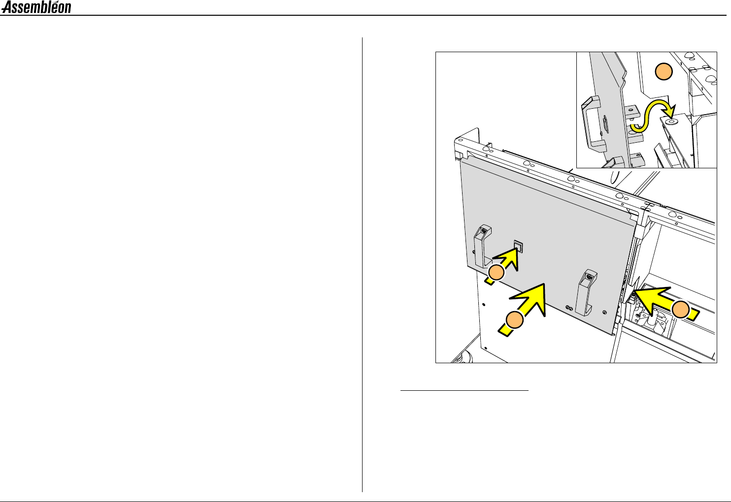
2.6 Feeder handling
2.6.1 Feeder handling on the A-series trolley
A Check if the surfaces of the feeder interface on both feeder and
trolley are clean from components and do not have any mechanical
damage.
B Check that the tape on the feeder is cut directly below the feeder.
C Check that the top foil is cut at least 100 mm below the feeder
D Place the top guide of the feeder in the required feeder slot
position (1). Use the numbering from 1 to 27.
Pull handle (2), keep the feeder straight and slide (3) the two
position-pins into the holes (4) until the clamping lever (5) locks
onto the locking axis of the trolley.
E If the feeder is placed correctly into the feeder trolley, the green
LED (1) blinks approximately 3 seconds where after it will remain
ON continuously.
Check/correct (with push button 3 or 4) the pick position of the
first component (2).
■ Remove a feeder in reverse order.
Figure 21 Feeder handling on the A-series trolley
>100 mm
A
1
4
2
3
5
D
1
3
4
2
B
D
E
C
4022 593 51894 Operating Manual
09.01 AX-301/501, AX-3/5 22
2
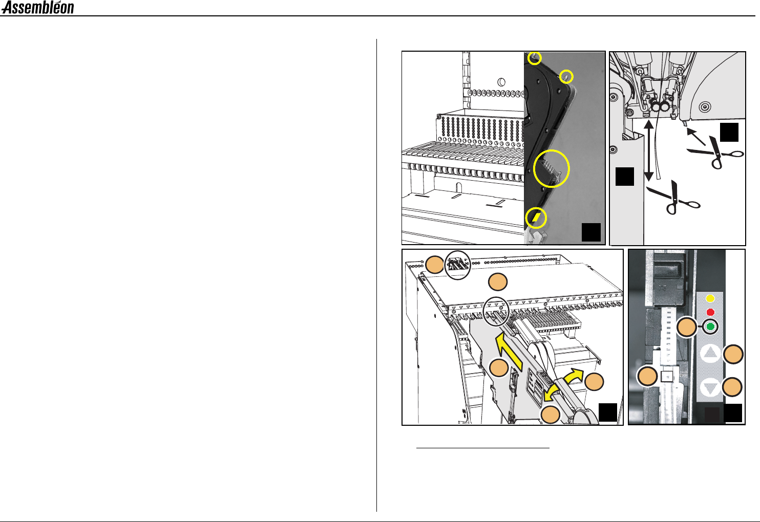
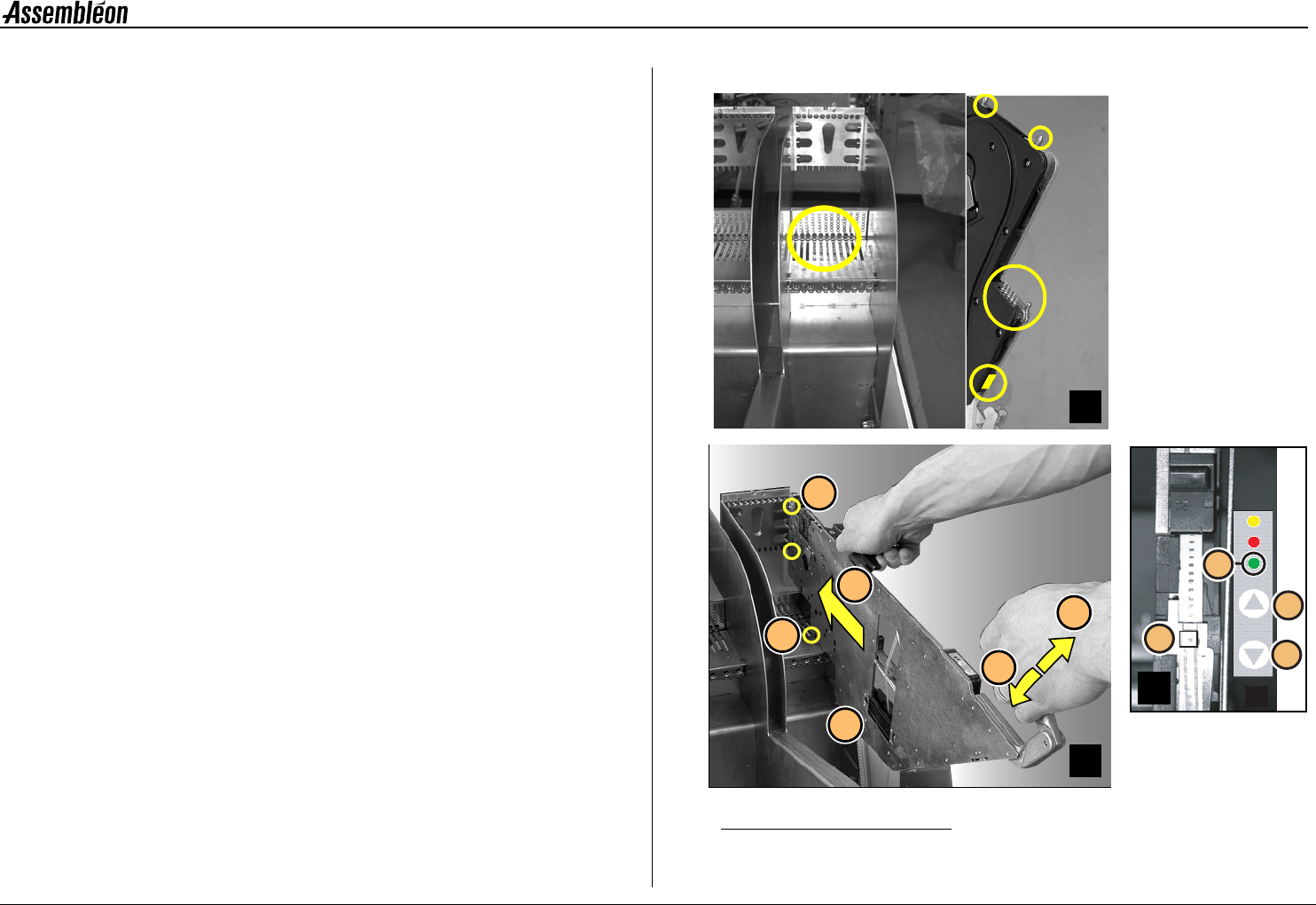
2.6.2 Feeder handling on the FCM-II trolley
A Check if the surfaces of the feeder interface on both feeder and
trolley are clean from components and do not have any mechanical
damage.
B Keep the feeder in horizontal position above the required feeder
slot position. Use the numbering from 1 to 44.
Lower the feeder, so the guide (1) will fall into the slotted hole.
Pull handle (2) and slide (3) the two position-pins into the holes
(4) until the clamping lever (5) locks onto the locking axis of the
trolley.
Make sure that the feeder runs straight and parallel with the slit
of the feeder bar during insertion.
C If the feeder is placed correctly into the feeder trolley, the green
LED (1) blinks approximately 3 seconds where after it will remain
ON continuously.
Check/correct (with push button 3 or 4) the pick position of the
first component (2).
■ Remove a feeder in reverse order.
Figure 22 Feeder handling
4
1
5
5
2
3
D
1
3
4
2
C
A
B