AX501最新3.6x版英文操作手册 - 第43页
4022 593 51894 Operatin g Man ual 09.01 AX-301/501, AX-3/5 43 10 • After th e probl em is solved sel ect one o f the options on th e right sid e of the inf ormation panel (3): - Retry all: r etry all displayed error s. -…
4022 593 51894 Operating Manual
09.01 AX-301/501, AX-3/5 42
10
CHAPTER 10 Error Handling
10.1 Errors and warnings, recognition
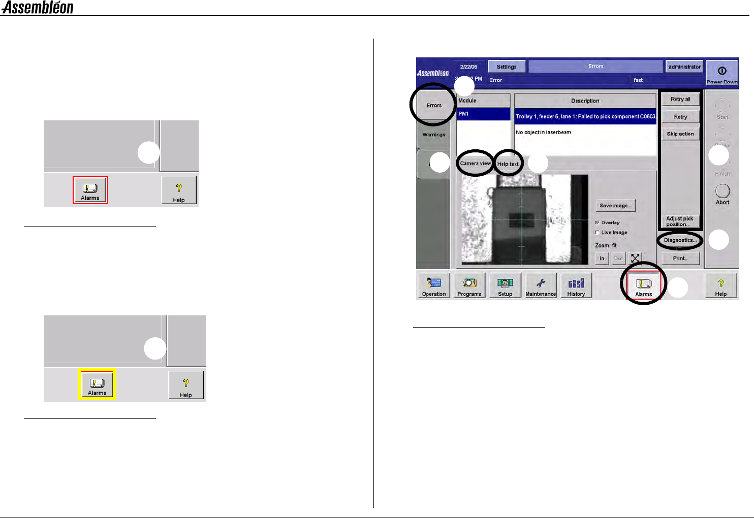
A coloured border shown around the alarm button indicates a machine or
process malfunction:
Figure 54 Error indication
•
A red border indicates an error (1).
Machine stopped, error has to be solved before production can
continue.
Beeps and Blue lamp on lamp post turn on.
Figure 55 Warning indication
•
A yellow border indicates a warning (2).
Machine proceeds, but problem should be solved for optimal
operation.
10.2 Display errors
Figure 56 Alarm screen selection
•
Select ’Alarms’ (1).
• Select ’Errors’ (2).
• Use available information on:
- Module(s) causing error(s) (A).
- Details on error(s) (B).
- Help instructions on selected error (C).
- Camera view related to the error situation (D),
see section 10.2.1. Camera view.
- Access to diagnostics environment (E),
see section 10.3.1. Diagnostics toolbox.
• Solve the problem on the machine.
1
2
2
3
1
A
B
D
C
E
4022 593 51894 Operating Manual
09.01 AX-301/501, AX-3/5 43
10
• After the problem is solved select one of the options on the
right side of the information panel (3):
- Retry all: retry all displayed errors.
- Retry: retry the selected error only.
- Skip action: skip action on module that is related to
the selected error.
Note that the options that are available depend on the errors that are
displayed. Only options that are applicable for the displayed errors are
visible.
NOTE: Selecting ‘Skip Action’ or ’Skip Board’ leads to incomplete
boards at the run-out. The message:
• ’Suspected board in Run-out’ or
• ’Skipped board in Run-out’ appears.
Remove or mark the board.
• After a retry the status of all modules involved is displayed.
When an error is not solved, the error screen will continue to
display the error. When all errors are solved, production will
resume automatically.
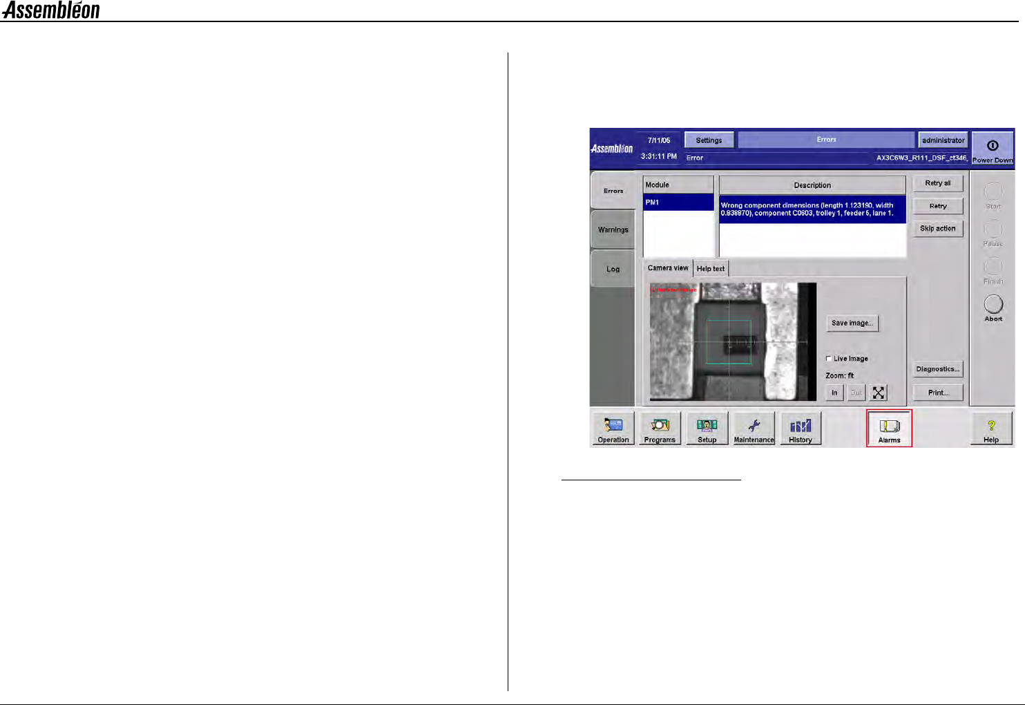
10.2.1 Camera view
Investigate the error situation using the 'camera view' option when
available (see figure 57).
Figure 57 Camera view related to the error situation
NOTE: Using the 'camera view' improves trouble shoot efficiency
by:
- No unnecessary machine handling (removal of feeder,
opening placement robot).
- Reduced recovery time by eliminating home procedures
after
opening robots or transport covers.
4022 593 51894 Operating Manual
09.01 AX-301/501, AX-3/5 44
10
10.3 Error solving procedures
10.3.1 Diagnostics toolbox
Figure 58 Diagnostics toolbox
Use the diagnostics environment to troubleshoot the error situation in
more detail.
Access to the diagnostic environment is restricted to qualified and
trained personnel of maintenance or service level only.
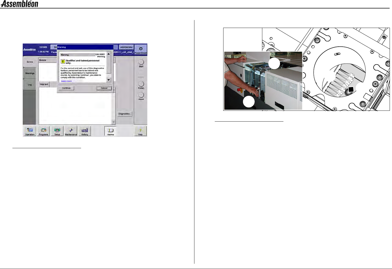
10.3.2 Air switch for CV camera
Figure 59 Air switch for CV camera
When an error states that a component (1) is blocking the camera view it
has to be blown away (2).
To remove this component from inside the CV camera, press the air switch
at the back of the machine.
1 Remove the top cover (4) at the back, where the CV camera is
located.
2 Press the air switch (3) positioned on top of the electrical distri-
bution rail.
10.4 Display warnings
Warnings are less important than errors: production can continue. In case
of a warning, note the warning and take action so the warning will be
solved and not result in an error.
1
2
3
4