00198521-01_UM_LDU_E_EN.pdf - 第16页
2 Operational safety 2.4 ESD guidelines 16 User Manual SIPLACE Linear Dipping Unit E 12/2018

2 Operational safety
2.4 ESD guidelines
User Manual SIPLACE Linear Dipping Unit E 12/2018 15
2.4.5 Dispatching ESD modules
► Always store modules and components in conductive packaging (e.g. metallized plastic bags
or metal sleeves) and dispatch them in conductive packaging.
► If the packaging is not conductive, place the modules in a conductive envelope before pack-
aging. Use conductive expanded rubber, ESD bags, domestic aluminum foil or paper, for ex-
ample. NEVER use plastic bags or film.
► If the module has integral batteries, ensure that the conductive packaging does not touch or
short circuit the battery terminals and, if necessary, first cover the terminals with insulating
tape or material.

2 Operational safety
2.4 ESD guidelines
16 User Manual SIPLACE Linear Dipping Unit E 12/2018
3 Function description and structure
3.1 Function description
User Manual SIPLACE Linear Dipping Unit E 12/2018 17
3 Function description and structure
3.1 Function description
The LDU is set up on a changeover table in the same way as any other feeder module. The line
software (SIPLACE Pro) can be used to select components for dipping and to set the relevant
parameters. The LDU makes the flux available in a certain area, in the pre-defined amount (layer
thickness). The layer of flux is always renewed by automatically performed application runs. This
ensures that the components are dipped in a fresh layer of flux and that consistent process condi-
tions are maintained.
The LDU can be roughly divided into a mechanical section - an application unit - and an electrical
section - the so-called control unit.
Control unit
The control unit contains the electrical parts, such as the power supply, interfaces, the control sys-
tem and the operating unit.
Application unit
The application unit has two movement axes. The squeegee axis moves a slide unit back and forth.
The lift axis moves the lift unit up and down. Both of these axes are driven by electrical motors and
a spindle system. A rotary encoder on the motor shaft determines the current position of the
spindle. Both axes have sensors which indicate when the axis reaches its end position.
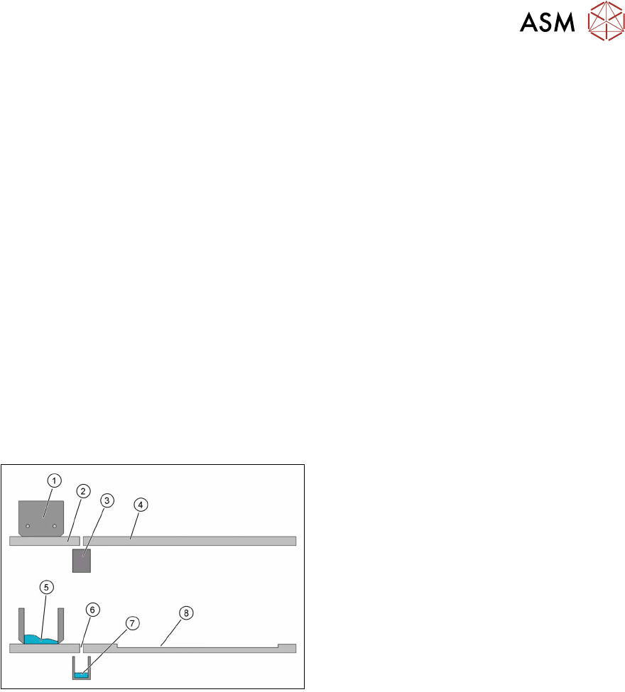
The application unit of the LDU consists of the
following main parts:
1. Flux tank
2. Park plate
3. Drip tray
4. Dip plate
5. Flux
6. Interface
7. Flux in the drip tray
8. Cavity