00198521-01_UM_LDU_E_EN.pdf - 第19页
3 Function description and structure 3.2 Structure User Manual SIPLACE Linear Dipping Unit E 12/2018 19 3.2 Structure 3.2.1 Housing 1. Handle 2. Emergency stop button 3. Rear cover 4. Control unit 5. Top cover 6. Cover o…
3 Function description and structure
3.1 Function description
18 User Manual SIPLACE Linear Dipping Unit E 12/2018
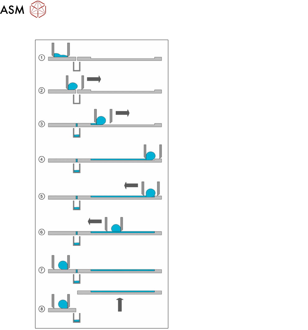
Application process
1. The application unit is in its basic position.
The flux tank is over the park plate, in the
park position. The tank has been filled with
new flux, which is now spreading over the
"base" of the flux tank. The dip plate is in
the application position.
2. The application begins. The slide unit with
the flux tank moves forward in the direction
of the dip plate. The flux in the tank forms
a roll, depending on its viscosity.
3. The flux tank reaches the dip plate cavity.
The flux is distributed in the cavity and
wiped off by the bottom edge of the flux
tank.
4. The slide unit moves to its reverse position
at the end of the dip plate. The whole cav-
ity is now filled with flux.
5. The slide unit moves back.
6. The flux roll now forms on the other side of
the flux tank. The edge strips off the layer
of flux applied to ensure that the flux layer
height remains constant.
7. The slide unit reaches the starting position
above the park plate. Any flux which may
have run into the gap in the interface area
will be caught by the drip tray.
8. The lift unit moves the dip plate out of the
application position and into the dip posi-
tion. The placement head can now dip the
components into the flux.
For the next application process the lift unit
moves the dip plate back in the application posi-
tion, then steps 1 to 8 will be repeated.
3 Function description and structure
3.2 Structure
User Manual SIPLACE Linear Dipping Unit E 12/2018 19
3.2 Structure
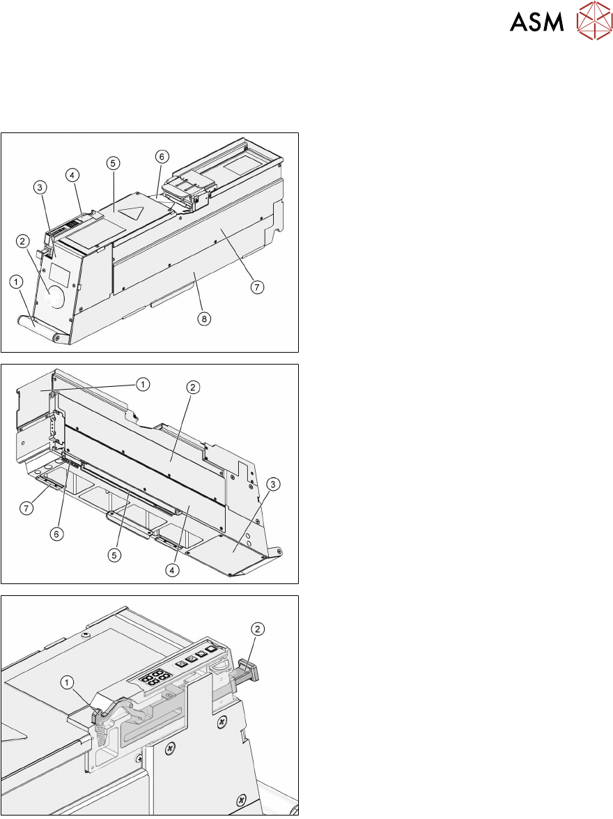
3.2.1 Housing
1. Handle
2. Emergency stop button
3. Rear cover
4. Control unit
5. Top cover
6. Cover of coupling
7. Right side panel
8. Body
1. Front cover
2. Left side panel
3. Bottom cover
4. Cover of control board
5. Rear slide bar
6. Front slide bar
7. Support block
1. Locking hook
2. Unlock handle
3 Function description and structure
3.2 Structure
20 User Manual SIPLACE Linear Dipping Unit E 12/2018
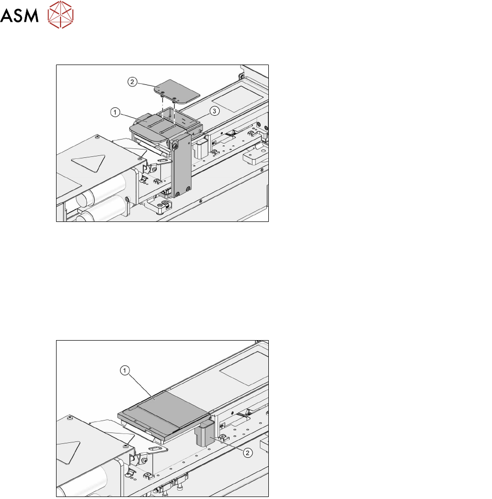
3.2.2 Squeegee
1. Downholder
2. Cover
3. Flux tank
The removable cover of the flux tank reduces any vaporization or drying out of the flux. The down-
holder holds the flux tank in the correct position. By pressing on the downholder the flux tank can
easily be removed.
The flux tanks available so far are still compatible with the LDU:
●
Standard tank [03060794-xx]
●
Small tank [03062326-xx]
3.2.3 Park plate and drip tray
1. Park plate
2. Drip tray
The park plate is held in place by permanent magnets. The shape of the drip tray is asymmetric so
that it cannot be fitted wrongly. Two sensors on the base determine whether a park plate or a drip
tray is fitted.