00198521-01_UM_LDU_E_EN.pdf - 第34页
4 Operation 4.1 Settings in the line software 34 User Manual SIPLACE Linear Dipping Unit E 12/2018 4.1.2 Assigning a flux to the LDU On one placement machine, several LDU units can be used. Each LDU can be filled with an…
4 Operation
4.1 Settings in the line software
User Manual SIPLACE Linear Dipping Unit E 12/2018 33
4 Operation
4.1 Settings in the line software
In order to use the LDU in a placement order, the following settings have to be defined in the line
software before start-up:
●
Setting up
●
Flux used
●
Dip parameters for the components used:
– Flux used
– Dip sequence
– Cavity depth of the dip plate
– Pressing force when dipping
– Dwell time when dipping
– Travel profile when dipping
– Waiting time at placement
●
Processing Parameters for the flux used:
– Cicatrization time
– Curing time
– Squeegee speed
– Number of squeegee cycles during the warm-up cycle
4.1.1 Setting up the LDU
●
The LDU cannot be set up in the 6 outer tracks on the right- and left-hand side of the
changeover table.
●
The LDU can be set up directly next to any feeder modules.
●
The LDU should not be configured in direct vicinity to feeder modules for very small compon-
ents.
●
It is recommended not to set up any linear feeder and stick feeder modules together with the
LDU on the same changeover table.
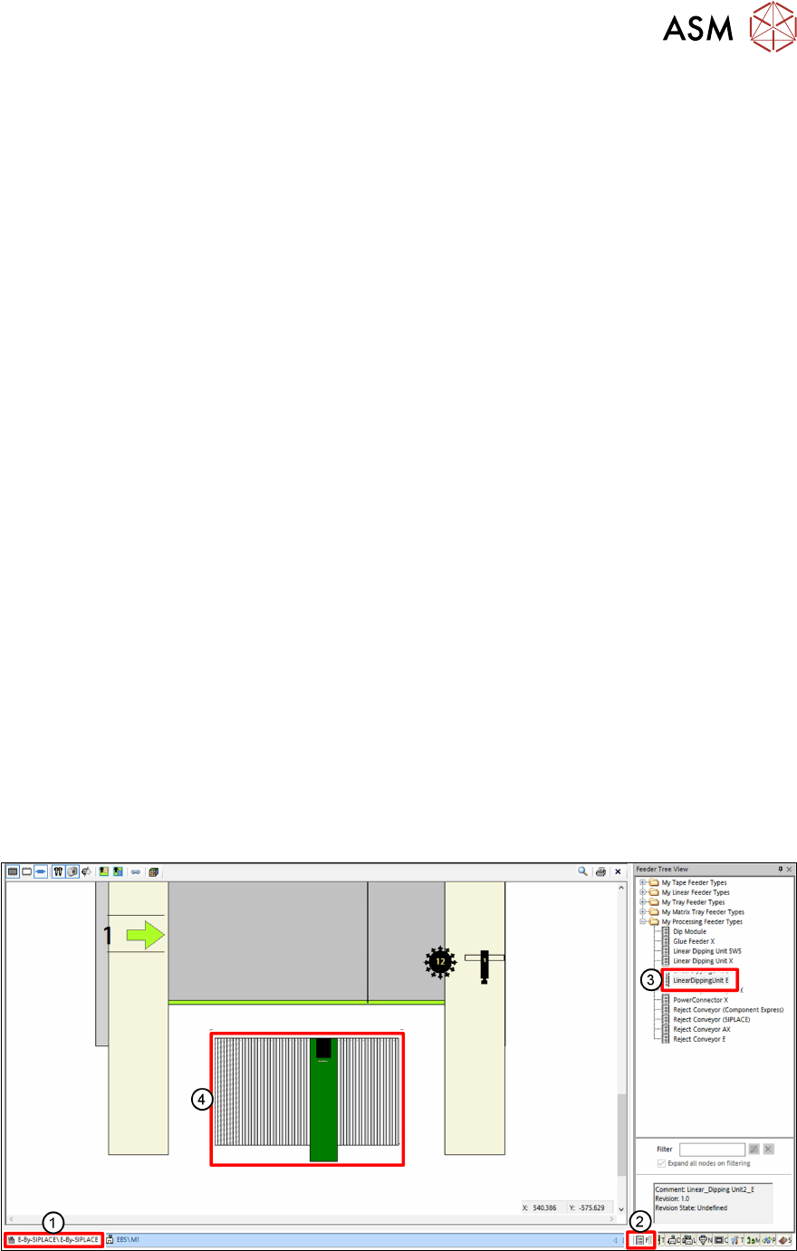
► In the line software, click on the Setup tab(1).
► Click on the Feeder Tree View tab(2).
► Drag the relevant LDU from the tree view(3) to the desired track of the changeover table(4).
4 Operation
4.1 Settings in the line software
34 User Manual SIPLACE Linear Dipping Unit E 12/2018
4.1.2 Assigning a flux to the LDU
On one placement machine, several LDU units can be used. Each LDU can be filled with another
flux. For this purpose, the user must assign the corresponding flux and the cavity depth of the dip
plate used to the LDU set up.
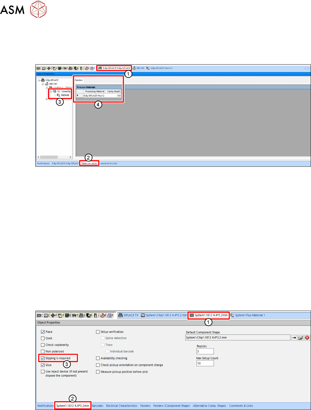
► In the line software, click on the Setup tab(1).
► Click on the Tables on setup tab(2) in the Object Properties view.
► Select the desired LDU in the tree view.
► Click on the Material entry(3).
► Click on the free field in the Process material column on the Feeder tab(4).
A button with three points is displayed.
► Click on the button with the three points.
A dialog window is displayed to select the flux.
► Click on the desired flux in the tree view.
► Click OK.
► On the Feeder tab(4), in the Cavity depth column, enter the cavity depth of the dip plate
used.
4.1.3 Selecting a component for dipping
For every component used, the user can set that dipping is required:
► In the line software, click on the tab of the desired component(1).
► Click on the tab of the component(2) in the Object Properties view.
► Enable the Dipping is required option(3).
4 Operation
4.1 Settings in the line software
User Manual SIPLACE Linear Dipping Unit E 12/2018 35
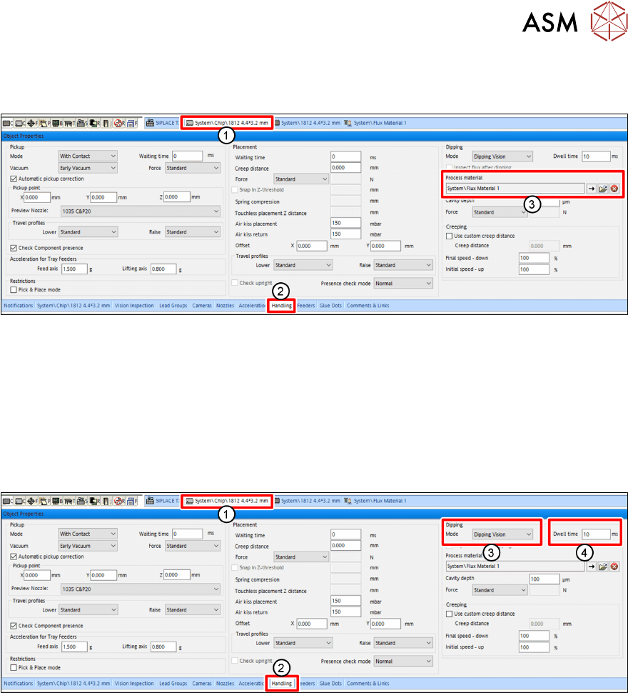
4.1.4 Assigning a flux to a component
The user must assign a flux to a component for which dipping is required.
► In the line software, click on the tab of the component shape of the desired component(1).
► Click on the Handling tab(2) in the Object Properties view.
► Click on the button with the arrow next to Process Material(3) in the Dipping area.
A dialog window is displayed to select the flux.
► Click on the desired flux in the tree view.
► Click on OK.
4.1.5 Setting the dip sequence and the dwell time
► In the line software, click on the tab of the component shape of the desired component(1).
► Click on the Handling tab(2) in the Object Properties view.
► Select the dip sequence under Mode(3) in the Dipping area.
► Enter the dwell time in milliseconds[ms] in the Dwell time field (4).
For more information on the dwell time, see chapter 3.3.6 "Dip process and dwell time" [}32].
For more information on the different dip sequences, see the online help of the line software.