00198521-01_UM_LDU_E_EN.pdf - 第36页
4 Operation 4.1 Settings in the line software 36 User Manual SIPLACE Linear Dipping Unit E 12/2018 4.1.6 Setting the cavity depth and the pressing force ► In the line software, click on the tab of the component shape of …
4 Operation
4.1 Settings in the line software
User Manual SIPLACE Linear Dipping Unit E 12/2018 35
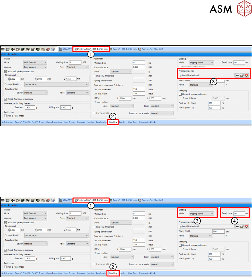
4.1.4 Assigning a flux to a component
The user must assign a flux to a component for which dipping is required.
► In the line software, click on the tab of the component shape of the desired component(1).
► Click on the Handling tab(2) in the Object Properties view.
► Click on the button with the arrow next to Process Material(3) in the Dipping area.
A dialog window is displayed to select the flux.
► Click on the desired flux in the tree view.
► Click on OK.
4.1.5 Setting the dip sequence and the dwell time
► In the line software, click on the tab of the component shape of the desired component(1).
► Click on the Handling tab(2) in the Object Properties view.
► Select the dip sequence under Mode(3) in the Dipping area.
► Enter the dwell time in milliseconds[ms] in the Dwell time field (4).
For more information on the dwell time, see chapter 3.3.6 "Dip process and dwell time" [}32].
For more information on the different dip sequences, see the online help of the line software.
4 Operation
4.1 Settings in the line software
36 User Manual SIPLACE Linear Dipping Unit E 12/2018
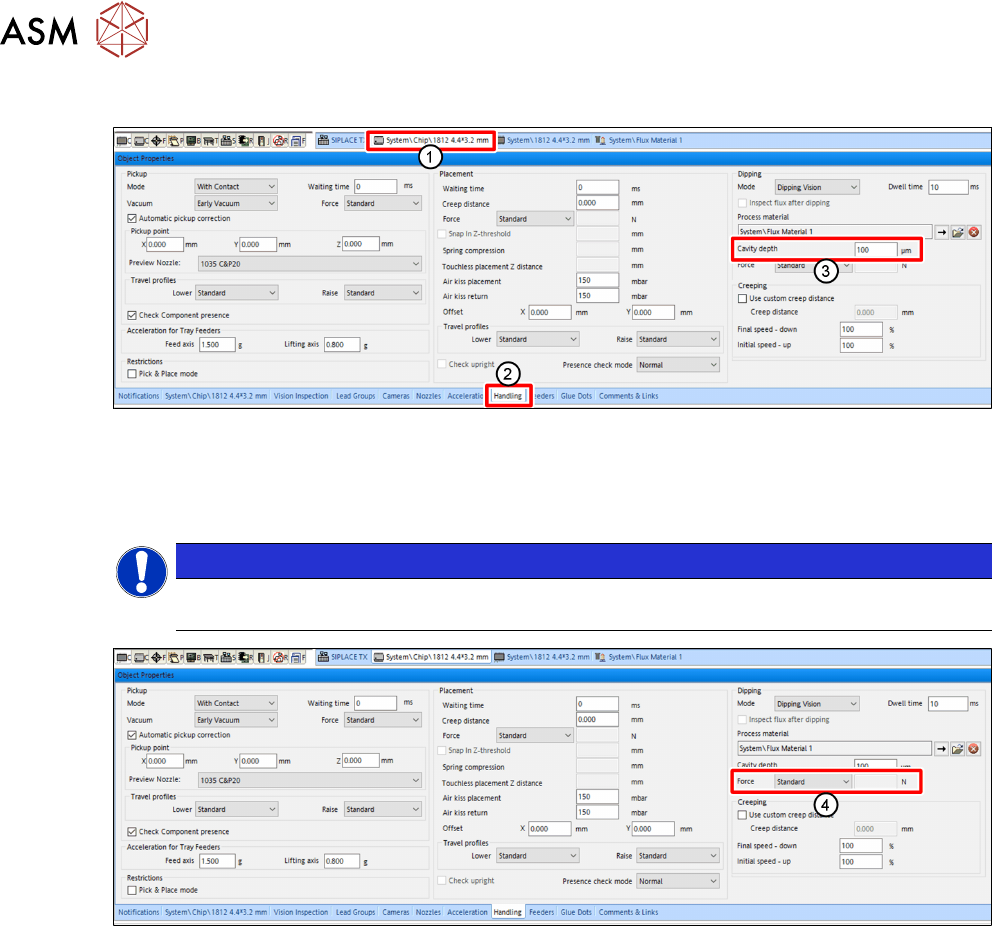
4.1.6 Setting the cavity depth and the pressing force
► In the line software, click on the tab of the component shape of the desired component(1).
► Click on the Handling tab(2) in the Object Properties view.
► Enter the cavity depth of the dip plate used in micrometers [µm] in the Cavity depth entry
field(3) in the Dipping area.
NOTICE
Ensure that you enter the same cavity depth that you already entered when assign-
ing a flux (see chapter 4.1.2 "Assigning a flux to the LDU" [
}
34]).
► In the Dipping area, from the Force menu (4), select the desired mode for the pressing force:
●
Standard
●
Specific
●
Very low
► If you select Specific, you can enter the desired pressing force in Newton [N] in the entry field
to the right.
4 Operation
4.1 Settings in the line software
User Manual SIPLACE Linear Dipping Unit E 12/2018 37
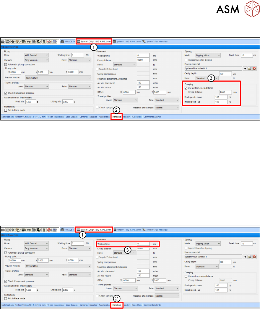
4.1.7 Setting the creep distance
► In the line software, click on the tab of the component shape of the desired component(1).
► Click on the Handling tab(2) in the Object Properties view.
► Enable the Use custom creep distance option(3) under Creeping(3) in the Dipping area.
► Enter the desired length of the creep distance in the Creep Distance entry field.
► In the Speed down end entry field, enter the desired speed down.
► In the Speed up start entry field, enter the desired speed up.
For more information to creep distance, speed down and speed up, see chapter 3.3.7 "Creep dis-
tance" [}32].
4.1.8 Setting the waiting time
Depending on the component and the flux used, it can be advantageous to hold the component on
the PCB for a short waiting time during the placement process.
► In the line software, click on the tab of the component shape of the desired component(1).
► Click on the Handling tab(2) in the Object Properties view.
► Enter the Waiting time in milliseconds [ms] in the Waiting Time entry field (3) in the Place-
ment area.