SG_FSE_SiplaceHF_HF3_00193901-05_eng.pdf - 第102页
1 - 32 S tudent Guide SIPLACE HF/HF3 3 Communication and Control Edition 09/2005 32 3.3.1 1 CAN: Bus Communicati on with Axis Controller In previous Siplace placement machin es, the communication and da ta flow between a…

1 - 31
Student Guide SIPLACE HF/HF3
Edition 09/2005 3 Communication and Control
31
I/O Modul SUB Distributor: (Outputs) 3
nc= not connected (Reserve)
Connectors I / O Description / Note
X7_1 Do0
St_D0ServoSlot Bit-0 of the servo slot identification
Each servo card get a number (0-16) for the Identification. This number can be
reconstructed from all 4 servo address bus messages. In the interaction with the
outputs EA2/Do0 to EA2/Do4 every servo board can be checked in the provided
slot.
X7_2 Do1
St_D1ServoSlot / Bit-1 of the ServoSlot-Identification!
X7_3 Do2
St_D2ServoSlot / Bit-2 of the ServoSlot-Identification!
X7_4 Do3
St_D3ServoSlot / Bit-3 of the ServoSlot-Identification!
X7_5 Do4
St_D4ServoSlot / Bit-4 of the ServoSlot-Identification!
X7_6 Do5
St_pressure air main valve / ON
"low" Signal open the valve
X7_7 Do6
nc
X7_8 Do7
nc
X8_1 Do8
nc
X8_2 Do9
nc
X8_3 Do10
nc
X8_4 Do11
nc
X8_5 Do12
X8_6 Do13
X8_7 Do14
X8_8 Do15
1 - 32
Student Guide SIPLACE HF/HF3
3 Communication and Control Edition 09/2005
32
3.3.11 CAN: Bus Communication with Axis Controller
In previous Siplace placement machines, the communication and data flow between axis control-
ler and machine controller was achieved using the SMP bus. From the HF machine generation
on, the SMP bus is no longer used with the axis system.
The communication between the axis controller modules is now achieved using the CAN Bus. All
information, which has to be transfered between these modules, is now on the CAN bus (e.g axis
parameter, target position, end signal, ...) This of course means that the number of single tele-
grams increases significantly compared with the amount of data exchange which has occurred
previously.
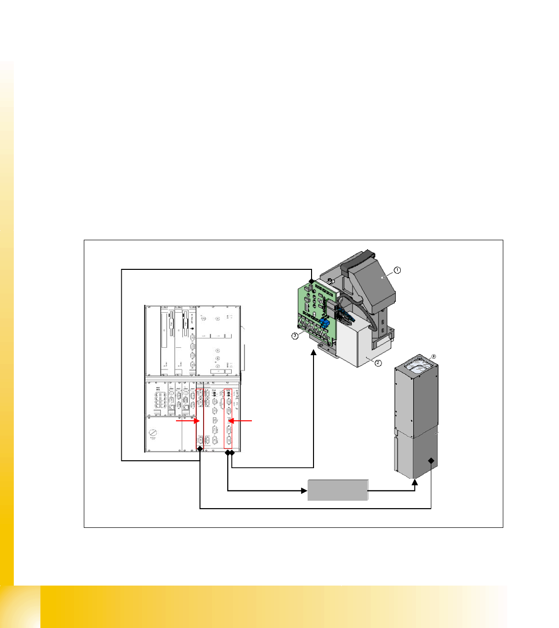
3.3.12 CAN Bus Communication with Vision system
The main communication between the vision system and CAN bus is the transmission of illumina-
tion values. These values, stored in the GF, are sent via CAN bus to the camera in question. As
soon as the camera should take the picture, the camera illumination is activated by a flash signal,
which travels in a single cable (flash line) to the camera. From this moment on the row of LEDs
which provide the different illumination levels light dependant on the illumination value 0-255. All
illumination levels start lighting at the same moment, triggered by the flash signal.
The value 0-255 determines the length of the illumination time.
The maximum length of illumination is limited to 6 ms.
Fig. 3.3 - 22 llumination values via CAN bus and cable for flash signal
5 V flash signal
CAN bus 1: telegram including illumination values
Com board
Vision
controller
Vision control
board section 2
CAN bus 2: telegram including illumination values
5 V flash signal
1 - 33
Student Guide SIPLACE HF/HF3
Edition 09/2005 3 Communication and Control
33
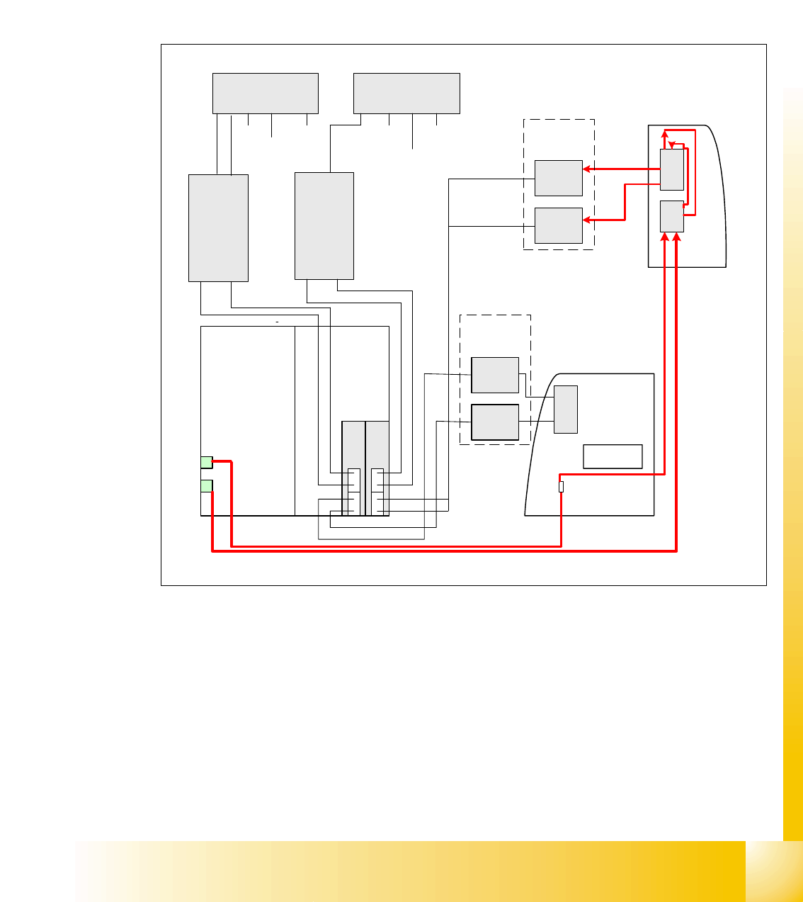
3.3.12.1 Visionsystem: Flash-Signal
The overview below shows the flash signals, triggered by the ICOS.
The flash signal for the stationary cameras, went via the vision control board (section 4, main dis-
tributor) to the camera in question and triggers the illumination.
The flash signal for the component camera revolving head uses the trailing cable to the vision
board on the head interface.
Fig. 3.3 - 23 flash overview
1
3
2
4
2
4
1
3
Backplane
Computerunit
x3pz
03004063
x15pz
03003434
ICOS 1
BB1
ICOS 2
BB2
Sector 4
Sector 2
Vision DC/
DC
Converter
Vision
Control unit
2
Vision
Control unit 1
03004063
03003434
Flash
x5qd
x4qd
03003435-W1
03003435-W2
FC-
Camera
IC-
Camera
Option
Connector
FC-
Camera
IC-
Camera
Option
BB 1 with
Twin head
x5rd
x4rd
03003439
03003440
03003450-W1
03003449-W2
03003438-W1
03003438-W2
BB 2 with
Twin head
Flash
Flash
Flash
x9
trailing
interface
Gantry 2
Visionboard BB1
on head interface
x9
Visionboard BB2
on head interface
x70 x80
03002507-W1
03002507-W2
03002508-W2
03002508-W1
x9
x3 x5 x4x3 x5 x4
PCB camera
Component
camera
PCB camera
Component camera
PCB
camera
Component
camera
PCB
camera
illumination
PCB
camera
illumination
PCB
camera
Component
camera
03001729
03001729
x9
trailing
interface
Gantry 1
x70 x80