SG_FSE_SiplaceHF_HF3_00193901-05_eng.pdf - 第104页
1 - 34 S tudent Guide SIPLACE HF/HF3 3 Communication and Control Edition 09/2005 34 Note
1 - 33
Student Guide SIPLACE HF/HF3
Edition 09/2005 3 Communication and Control
33
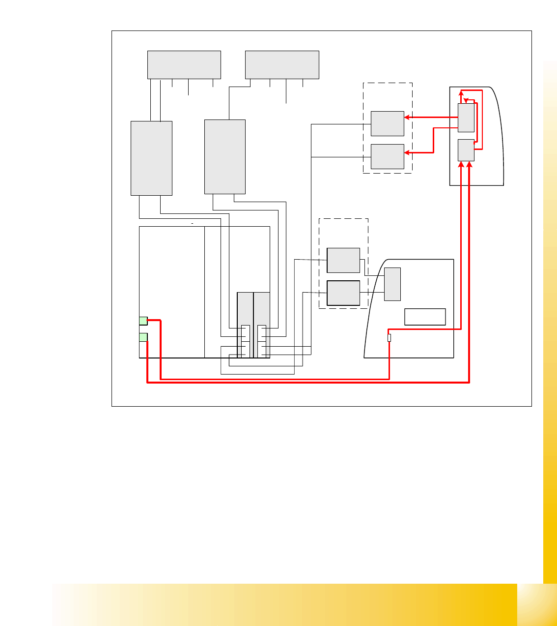
3.3.12.1 Visionsystem: Flash-Signal
The overview below shows the flash signals, triggered by the ICOS.
The flash signal for the stationary cameras, went via the vision control board (section 4, main dis-
tributor) to the camera in question and triggers the illumination.
The flash signal for the component camera revolving head uses the trailing cable to the vision
board on the head interface.
Fig. 3.3 - 23 flash overview
1
3
2
4
2
4
1
3
Backplane
Computerunit
x3pz
03004063
x15pz
03003434
ICOS 1
BB1
ICOS 2
BB2
Sector 4
Sector 2
Vision DC/
DC
Converter
Vision
Control unit
2
Vision
Control unit 1
03004063
03003434
Flash
x5qd
x4qd
03003435-W1
03003435-W2
FC-
Camera
IC-
Camera
Option
Connector
FC-
Camera
IC-
Camera
Option
BB 1 with
Twin head
x5rd
x4rd
03003439
03003440
03003450-W1
03003449-W2
03003438-W1
03003438-W2
BB 2 with
Twin head
Flash
Flash
Flash
x9
trailing
interface
Gantry 2
Visionboard BB1
on head interface
x9
Visionboard BB2
on head interface
x70 x80
03002507-W1
03002507-W2
03002508-W2
03002508-W1
x9
x3 x5 x4x3 x5 x4
PCB camera
Component
camera
PCB camera
Component camera
PCB
camera
Component
camera
PCB
camera
illumination
PCB
camera
illumination
PCB
camera
Component
camera
03001729
03001729
x9
trailing
interface
Gantry 1
x70 x80

1 - 35
Student Guide SIPLACE HF/HF3
Edition 09/2005 3 Communication and Control
35
3.4 Axis control
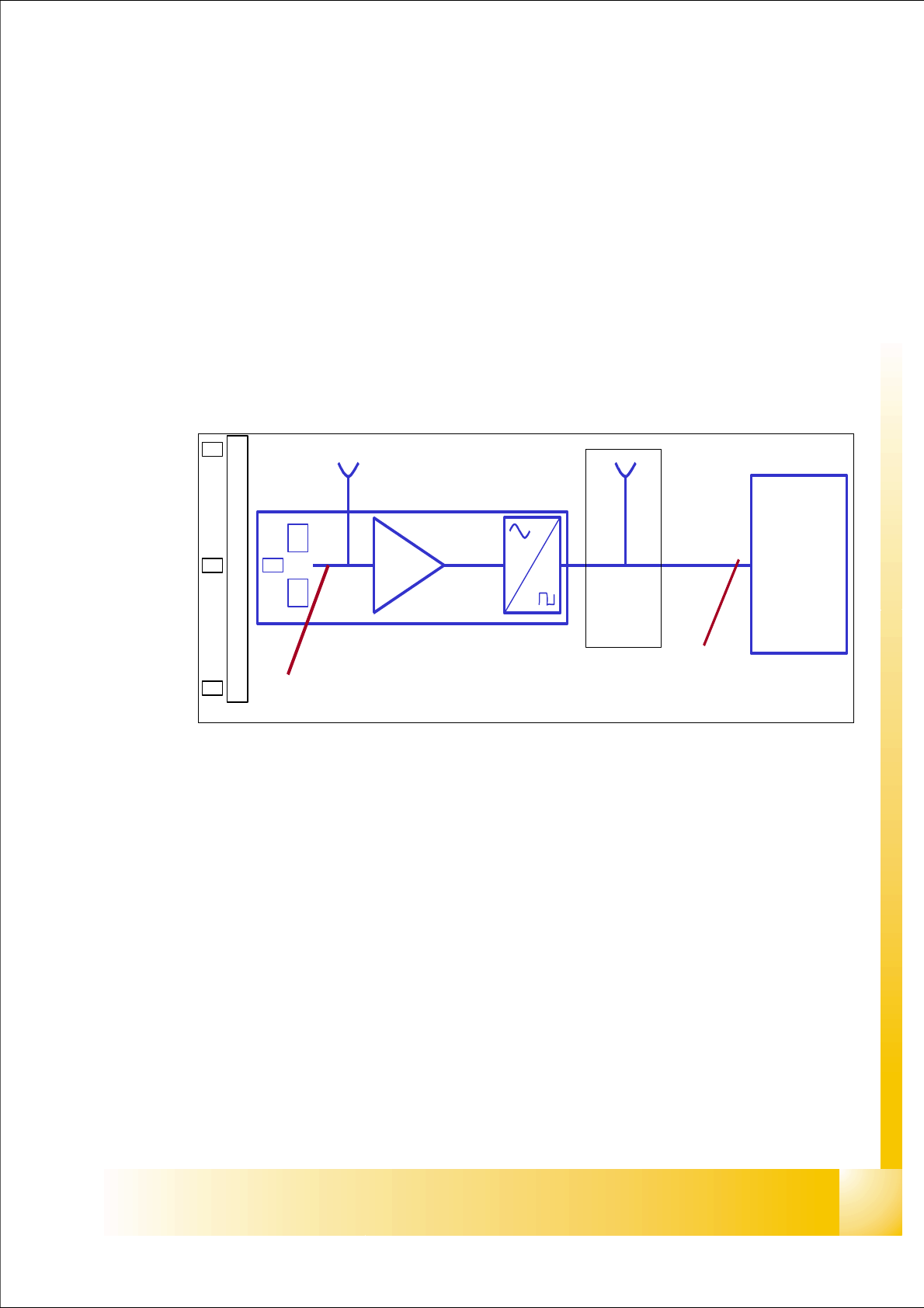
3.4.1 Position measuring system
3.4.1.1 Track signals and Zero pulse signal
Our Axes systems consists of the following parts.
– Axis controller board with VC 3 Controller
– Servo amplifier
– Motor
– Position measuring system with Incremental- scale and -encoder
Fig. 3.4 - 1 Principle circuit for position measuring systems
Legend
The closed-loop control system of an axis is detecting the position directly at the moving element
of the axis. The position measuring system generates an analoge signal when the encoder moves
over the scale. By standard an amplifier, a multiplication circuit and digitalization is integrated in
the encoder case. A test connector is normally available at the next interface board, or the digital
signals are measurable at the Track A / B and Zero pulse output of the SIPLACE Axis Tester.
At the HF-machine the track signals are the only feedback from the Axis to the control unit. This
means any fault on the track signals may influence the Axis control; the Gantry axes immediately
stops at a fault; the head axes finish the positioning to target before showing a track signal error.
(1) Incremental scale with zero pulses (2) Incremental encoder for track A / B and Zeropulse
signals (O-pulse.)
(3) Analoge signal output and amplifier (4) Electronic signal multiplication and signal digita-
lization
(5) Test output digital signals (6) Axis controller
A
B
A /A
B /B
0 -impuls .
/0-im
p
uls .
0 -impuls
1
2
3
4
5
6