SG_FSE_SiplaceHF_HF3_00193901-05_eng.pdf - 第105页
1 - 35 S tudent Guide SIPLACE HF/HF3 Edition 09/2005 3 Communication and Control 35 3.4 Axis control 3.4.1 Position measuring system 3.4.1.1 T rack signals and Zero pulse signal Our Axes systems cons ists of the followin…

1 - 35
Student Guide SIPLACE HF/HF3
Edition 09/2005 3 Communication and Control
35
3.4 Axis control
3.4.1 Position measuring system
3.4.1.1 Track signals and Zero pulse signal
Our Axes systems consists of the following parts.
– Axis controller board with VC 3 Controller
– Servo amplifier
– Motor
– Position measuring system with Incremental- scale and -encoder
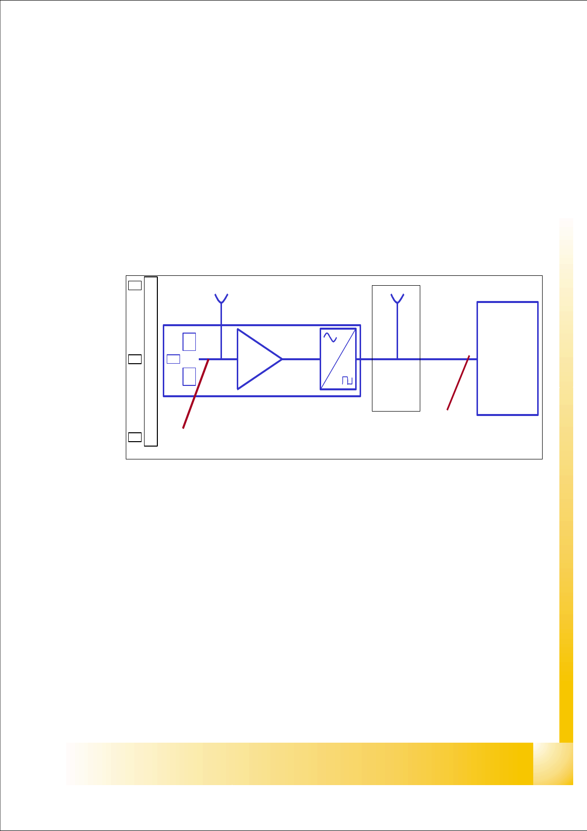
Fig. 3.4 - 1 Principle circuit for position measuring systems
Legend
The closed-loop control system of an axis is detecting the position directly at the moving element
of the axis. The position measuring system generates an analoge signal when the encoder moves
over the scale. By standard an amplifier, a multiplication circuit and digitalization is integrated in
the encoder case. A test connector is normally available at the next interface board, or the digital
signals are measurable at the Track A / B and Zero pulse output of the SIPLACE Axis Tester.
At the HF-machine the track signals are the only feedback from the Axis to the control unit. This
means any fault on the track signals may influence the Axis control; the Gantry axes immediately
stops at a fault; the head axes finish the positioning to target before showing a track signal error.
(1) Incremental scale with zero pulses (2) Incremental encoder for track A / B and Zeropulse
signals (O-pulse.)
(3) Analoge signal output and amplifier (4) Electronic signal multiplication and signal digita-
lization
(5) Test output digital signals (6) Axis controller
A
B
A /A
B /B
0 -impuls .
/0-im
p
uls .
0 -impuls
1
2
3
4
5
6
1 - 36
Student Guide SIPLACE HF/HF3
3 Communication and Control Edition 09/2005
36
The position is determined by a position counter on the axis controller. The moving direction of the
axis is determined by the phase shift of the Tracksignals (a leading Track A signal means moving
to the right; a leading Track B signal means moving to the left).
To make the encoder system robust for the high resolution we multiply the frequency of the ana-
loge signal and create a high resolution digital measuring system.
Fig. 3.4 - 2 Principle signal multiplication at analog Track signals of a gantry axis
Legend
In principle the track signal is multiplied by a ’Schmitt Trigger’ circuit. By comparing analoge and
digital signals on our axes you will find a multiplication by 25 (see Fig. 3.4 - 2), 10 or by 1.
The track signals of the C&P head axes can only be measured as digital signals i.e. the transfor-
mation of the analogue track signals into digital track signals occurs directly in the incremental en-
coder without any Test connector in that encoder case.
(1) Analoge track A signal Incremental
encoder
(2) Analoge track B signal Incremental
encoder
(3) Digital track A signal at Test connector (4) Digital track B signal at Test connector
(5) Period time of analoge track signal (6) Period time of digital track signal
1
2
5
6