SG_FSE_SiplaceHF_HF3_00193901-05_eng.pdf - 第108页
1 - 38 S tudent Guide SIPLACE HF/HF3 3 Communication and Control Edition 09/2005 38 3.4.2 Axis dynamic basics Each axis start s from s position with acceleration a const ant speed phase and deceleration should move the a…
1 - 37
Student Guide SIPLACE HF/HF3
Edition 09/2005 3 Communication and Control
37
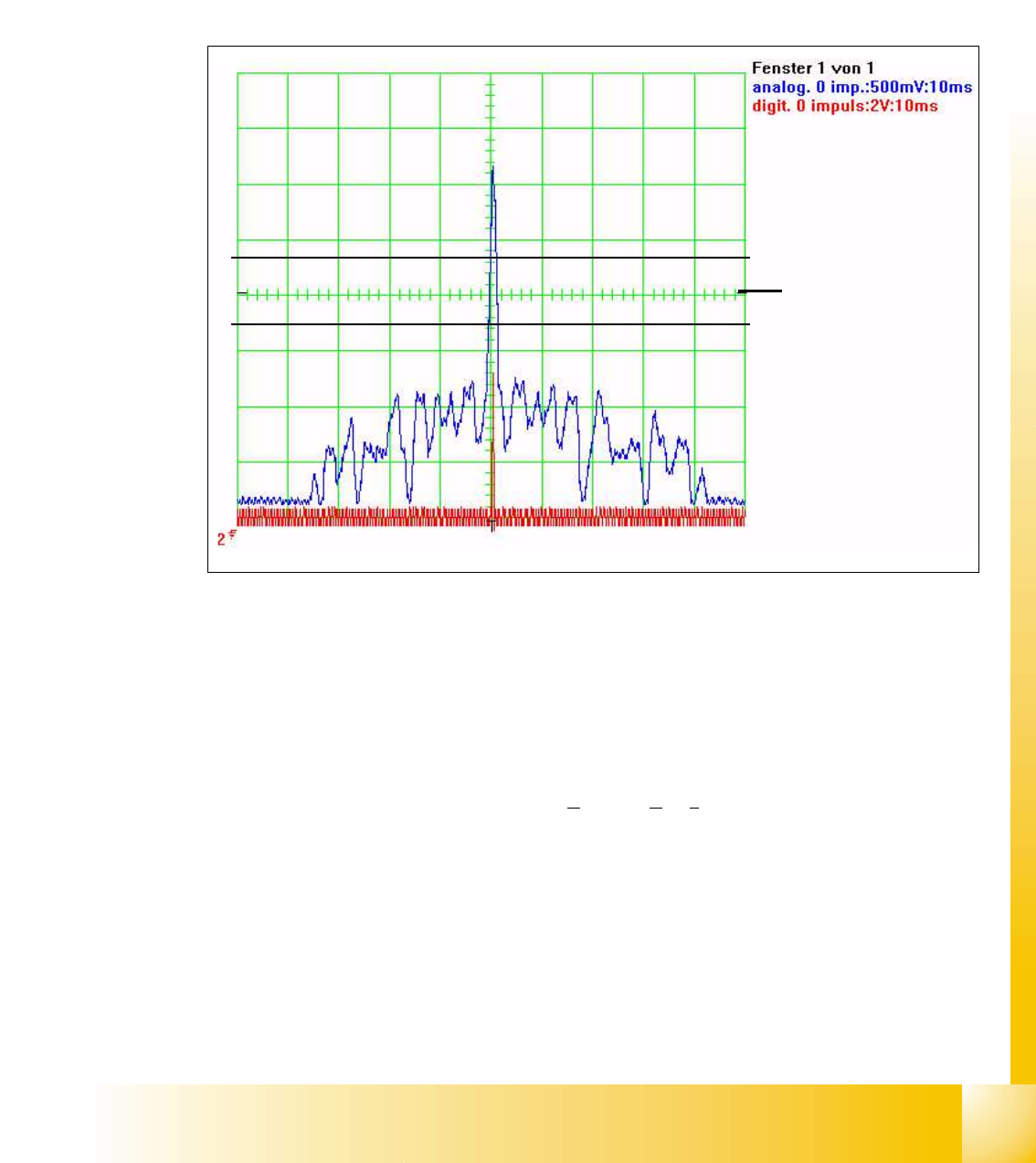
3.4.1.2 Zero pulse at the position encoder
Each incremental encoder system needs initializing. This mean a reference run is executed for
each axis.
At the reference run the system searches for a certain position - the signal for this is the Zero
pulse. The Zero pulse is an analoge signal and a ’Schmitt Trigger’ circuit digitizes it.
(calibrate ’Zero line’ to the middle of the screen before this measurement).
Fig. 3.4 - 3 Analoge and digital zero pulse signals (’zero line’ adjusted to middle)
At about 2.5 V threshold the ’Schmitt Trigger’ circuit creates a short high peak, the Zero pulse for
the position control system. If the encoder is mounted to close to the scale one of the noise glit-
ches could override the ’Schmitt Trigger’threshold. This means the Zero pulse is detected at a
wrong position of the Gantry axis, so it could lead to a board offset. (At S or HS machines this
could lead to a placement offset .) The digital Zero pulse is measured with a probe at Pin 8 of the
test connector.
The Zero pulse output of the Axistestbox (or S
IPLACE Axis Tester SAT ) is where the inverted
Zero pulse can be measured.
3
The analoge Zero pulse
has to be 0.3 V higher
than the Trigger threshold
for the digital pulse
Schmitt Trigger Threshold
Glitches (signal noise)
should not override the limit
0.3 V less than Trigger
threshold!
1 - 38
Student Guide SIPLACE HF/HF3
3 Communication and Control Edition 09/2005
38
3.4.2 Axis dynamic basics
Each axis starts from s position with acceleration a constant speed phase and deceleration should
move the axis into a target position. The dynamic movement is completely digital controlled at the
HF machines. A powerful digital processor permanently adjusts the axis behavior to each state of
axis dynamic. This mean all adjustments like speed (Tacho) and positioning quality (P-gain) at
servo amplifier are removed. The control signals are different for this new axis control principle.
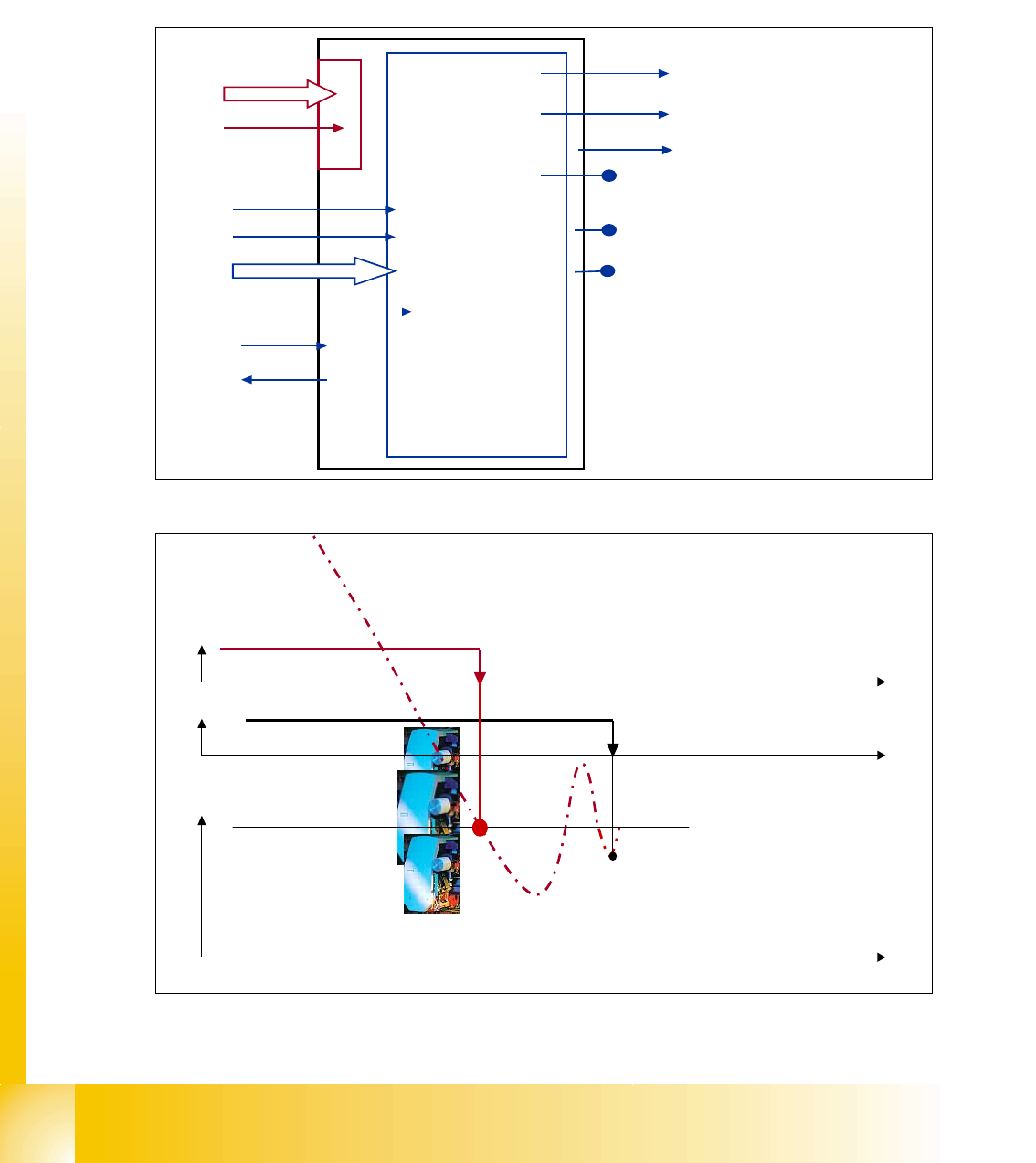
Fig. 3.4 - 4 Digital controlled axis at HF
Fig. 3.4 - 5 Positioning with overshoot into target position
I for Light barrier bottom
Servo Ready
position data
start
Track signals
Force value
Control signal 1 Servo
Control signal 2 Servo
Servo ON
Current measuring point
uncommutated current signal (V
reg
)
output V
nominal
output force
End signal
Axis
controller
at main
board
VC 3 controller
Act. pos. equal
nomial pos.
-
signal
target position
t
END-signal
Axis mechanic
within tolerable
position deviation
Position counter
count into target.
Overshoot 1 ‘15’
Overshoot 2 ‘-8’
Overshoot 2 ‘3’
t
t
1 - 39
Student Guide SIPLACE HF/HF3
Edition 09/2005 3 Communication and Control
39
Please Note:
The position deviation signal shows the positioning quality of an axis movement in position. 3
With the first positioning into the Target the ’actual position - equal nominal position’ signal is
available to trigger the ’overshoot counting’ at the Axistestbox (SAT) for the position deviation si-
gnal.
The known ’V nominal ’ speed signal and the ’force’ force limit signal are replaced by motor phase
nominal current signals to the DC respective AC Drive.
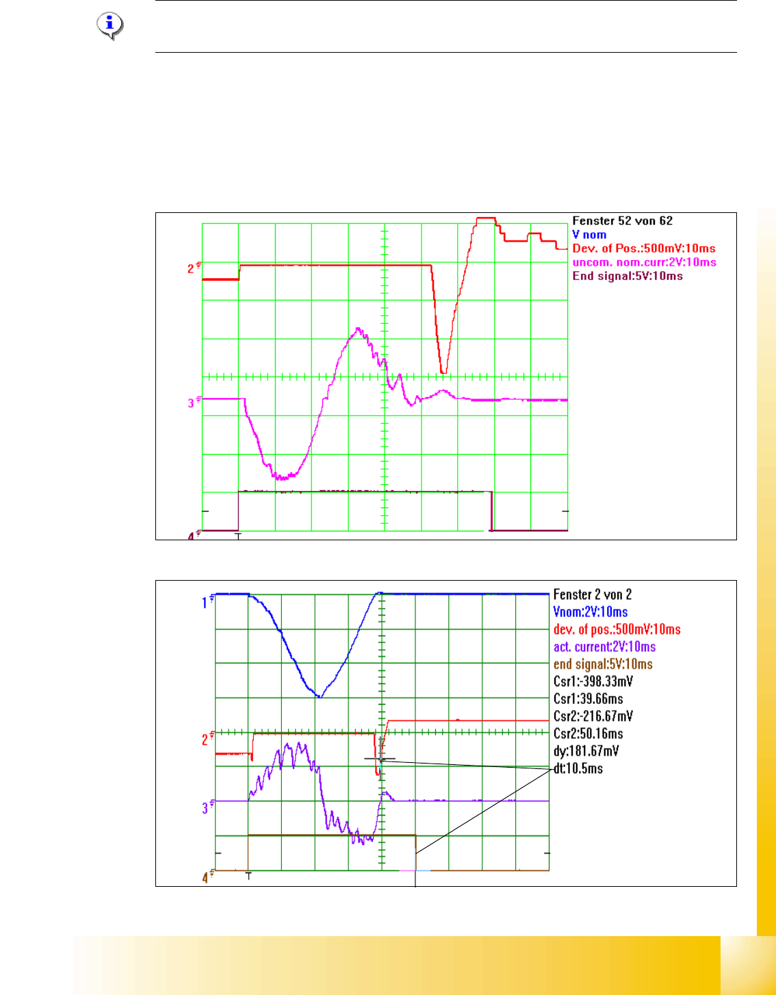
Fig. 3.4 - 6 2nd Overshoot set the end signal
Fig. 3.4 - 7 Positioning with asymtotic approach after 1 to high overshoot
1
2