SG_FSE_SiplaceHF_HF3_00193901-05_eng.pdf - 第109页
1 - 39 S tudent Guide SIPLACE HF/HF3 Edition 09/2005 3 Communication and Control 39 Please Note: The position deviation signal sho ws the position ing q uality of an axis movement in position. 3 With the first positionin…
1 - 38
Student Guide SIPLACE HF/HF3
3 Communication and Control Edition 09/2005
38
3.4.2 Axis dynamic basics
Each axis starts from s position with acceleration a constant speed phase and deceleration should
move the axis into a target position. The dynamic movement is completely digital controlled at the
HF machines. A powerful digital processor permanently adjusts the axis behavior to each state of
axis dynamic. This mean all adjustments like speed (Tacho) and positioning quality (P-gain) at
servo amplifier are removed. The control signals are different for this new axis control principle.
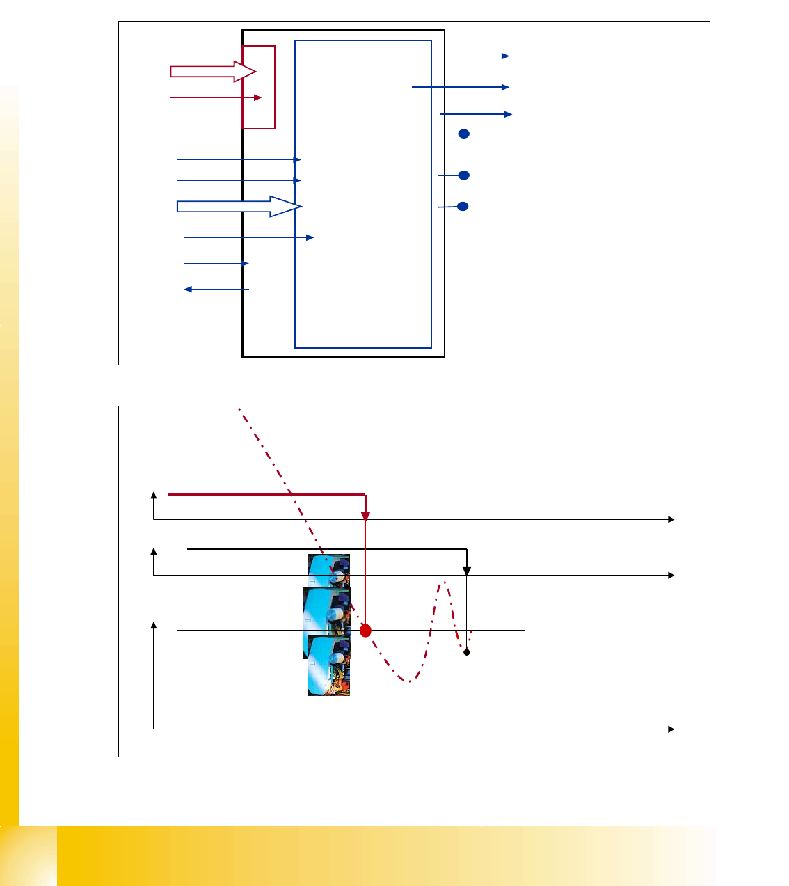
Fig. 3.4 - 4 Digital controlled axis at HF
Fig. 3.4 - 5 Positioning with overshoot into target position
I for Light barrier bottom
Servo Ready
position data
start
Track signals
Force value
Control signal 1 Servo
Control signal 2 Servo
Servo ON
Current measuring point
uncommutated current signal (V
reg
)
output V
nominal
output force
End signal
Axis
controller
at main
board
VC 3 controller
Act. pos. equal
nomial pos.
-
signal
target position
t
END-signal
Axis mechanic
within tolerable
position deviation
Position counter
count into target.
Overshoot 1 ‘15’
Overshoot 2 ‘-8’
Overshoot 2 ‘3’
t
t
1 - 39
Student Guide SIPLACE HF/HF3
Edition 09/2005 3 Communication and Control
39
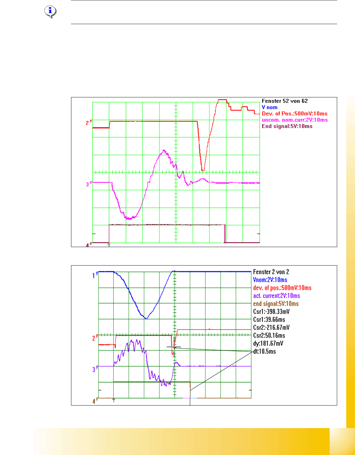
Please Note:
The position deviation signal shows the positioning quality of an axis movement in position. 3
With the first positioning into the Target the ’actual position - equal nominal position’ signal is
available to trigger the ’overshoot counting’ at the Axistestbox (SAT) for the position deviation si-
gnal.
The known ’V nominal ’ speed signal and the ’force’ force limit signal are replaced by motor phase
nominal current signals to the DC respective AC Drive.
Fig. 3.4 - 6 2nd Overshoot set the end signal
Fig. 3.4 - 7 Positioning with asymtotic approach after 1 to high overshoot
1
2
1 - 40
Student Guide SIPLACE HF/HF3
3 Communication and Control Edition 09/2005
40
The positioning in Fig. 3.4 - 7 has no large overshoot, so no other overshoot in the allowed range
happens overshoot control does not create an endsignal. The Axis controller has a ’backup stra-
tegy’ - entering the allowed deviation of position the axis controller sets a 10ms Timer, 10 ms after
entering the allowed position deviation range (1) (5 Digit) the Timer triggers the endsignal(2).
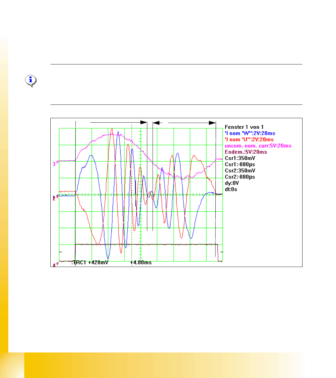
For the dynamic assesment of a service engineer an envelope signal to the nominal current si-
gnal(s) gives an idea on the mechanical friction in the Axis system. This signal is measurable on
the adapter board of the Axis test box or at the Vreg output of the Siplace AxisTester (SAT).
The ’uncommutated nominal current signal’ is the envelope signal to the 2 nominal motor currrent
signals the axis controller creates to control the mechanical movement of the motor. The missing
3rd motor current signal is calculated at the Servoboard.
The known ’V nominal ’ speed signal and the ’force’ force limit signal are replaced by motor phase
nominal current signals to the DC respective AC Drive.
Please Note:
These motor current signals are measurable at the V nominal- and the Force output at the Axis
Tester. The same signals are measurable at the 2 uppermost Testpin on the Servo board ’InomU’
’InomW’
Fig. 3.4 - 8 The uncommutaded nominal current signal (3) and the motor current signals (1) (2) of a AC Motor
The motor current signals for a AC Motor start the acceleration (1) with high amplitudes to acce-
lerate the axis mechanic the correct way. The frequency of this signal part is low because the axis
speed is low to. The amplitude becomes lower and lower because the necessary motor force is
reduced with increasing speed.
The frequency becomes higher because the speed of the motor is increased to a maximum for
the constant speed section (2).
1
2
3