SG_FSE_SiplaceHF_HF3_00193901-05_eng.pdf - 第114页
1 - 44 S tudent Guide SIPLACE HF/HF3 3 Communication and Control Edition 09/2005 44 Note
1 - 43
Student Guide SIPLACE HF/HF3
Edition 09/2005 3 Communication and Control
43
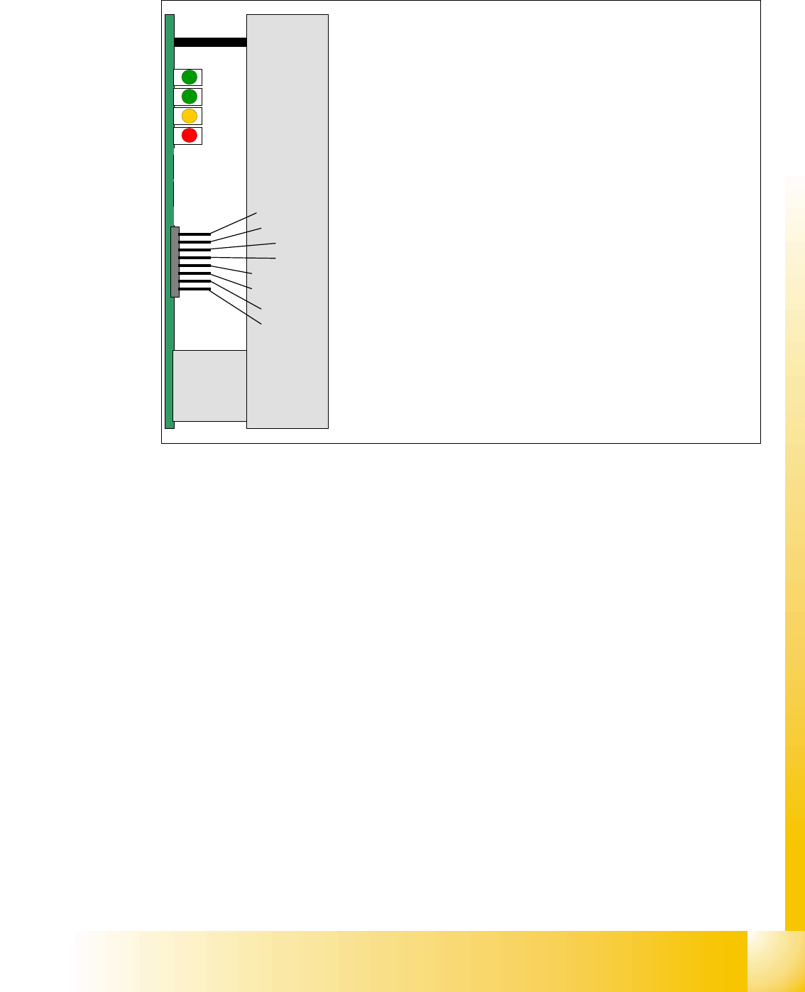
3.4.3.1 Servo amplifier TBS .. and SDS ...
Fig. 3.4 - 11 Servo amplifier
This SDS and TBS Servo amplifiers are to reset by Servo disable / Servo enable at Axis controller
board.
All Servos special adjusted to the maximum current of the drive motor of the refering axis type.
This mean the servo amplifiers have to be mount axis specifically.
Nominal current I
U
Nominal current I
W
Actual current I
U
Actual current I
W
Outp. Current controller Voltage V
U
Outp. Current controller Voltage V
W
Error
GND
Ready
Servo Enable
I
RMS
error
Board error
The nominal current signals also measurable at V nominal / Force
output of Axis controller
The Pin 3/4 show the actual current signals to the motor.
This signals are 180° phaseshifted to the nominal signal.
The Pin 5/6 show the voltages to drive the sinusoidal current
Ready is ON when Machine is ON
Servo Enable is first activated with a start of reference run. At X/Y
axis it is disabled after 2 min. without action and at Service posi-
tion.
I RMS error light up at short over current pulses.
Board error is a ’permanent’ error like over voltage / over current /
over temperature.


Student Guide SIPLACE HF/HF3
Edition 09/2005 Contents
1
Chapter
Table of Contents
4 Services to the machine. . . . . . . . . . . . . . . . . . . . . . . . . . . . . . . . . . . . . . . . . . . . . . 3
4.1 Overview. . . . . . . . . . . . . . . . . . . . . . . . . . . . . . . . . . . . . . . . . . . . . . . . . . . . . . . . . . . . . . . . . . . . . . . 3
4.1.1 Overview power supply . . . . . . . . . . . . . . . . . . . . . . . . . . . . . . . . . . . . . . . . . . . . . . . . 4
4.2 Power Supply on HF . . . . . . . . . . . . . . . . . . . . . . . . . . . . . . . . . . . . . . . . . . . . . . . . . . . . . . . . . . . . . 7
4.2.1 Naming Convention of Connectors and Cables . . . . . . . . . . . . . . . . . . . . . . . . . . . . . 7
4.2.2 Main distribution Unit, section 2. . . . . . . . . . . . . . . . . . . . . . . . . . . . . . . . . . . . . . . . . . 8
4.2.3 Sub distribution Unit, section 4 . . . . . . . . . . . . . . . . . . . . . . . . . . . . . . . . . . . . . . . . . . 9
4.2.4 Power Supply Unit. . . . . . . . . . . . . . . . . . . . . . . . . . . . . . . . . . . . . . . . . . . . . . . . . . . 10
4.2.4.1 Input Voltage . . . . . . . . . . . . . . . . . . . . . . . . . . . . . . . . . . . . . . . . . . . . . . . . . . . 13
4.2.4.2 Transformer 1. . . . . . . . . . . . . . . . . . . . . . . . . . . . . . . . . . . . . . . . . . . . . . . . . . . 14
4.2.4.3 Transformer 2. . . . . . . . . . . . . . . . . . . . . . . . . . . . . . . . . . . . . . . . . . . . . . . . . . . 15
4.2.4.4 Voltages in the Power Supply Unit after switching on . . . . . . . . . . . . . . . . . . . . 16
4.2.4.5 DC/DC Converter in Main Power Supply . . . . . . . . . . . . . . . . . . . . . . . . . . . . . . 17
4.2.5 Power Supply Computer Unit . . . . . . . . . . . . . . . . . . . . . . . . . . . . . . . . . . . . . . . . . . 18
4.2.6 Power Supply Axis Unit. . . . . . . . . . . . . . . . . . . . . . . . . . . . . . . . . . . . . . . . . . . . . . . 19
4.2.7 DC/DC Converter Vision section 2 . . . . . . . . . . . . . . . . . . . . . . . . . . . . . . . . . . . . . . 20
4.2.7.1 Power Supply Tape Cutter . . . . . . . . . . . . . . . . . . . . . . . . . . . . . . . . . . . . . . . . . 20
4.2.8 Safety and Control Loop(HF/HF3 bis MA.Nr. xx) . . . . . . . . . . . . . . . . . . . . . . . . . . . 21
4.2.8.1 Émergency Stop Loop (safety loop). . . . . . . . . . . . . . . . . . . . . . . . . . . . . . . . . . 21
4.2.8.2 Control loop . . . . . . . . . . . . . . . . . . . . . . . . . . . . . . . . . . . . . . . . . . . . . . . . . . . . 22
4.2.8.3 How does the emergency stop loop work?. . . . . . . . . . . . . . . . . . . . . . . . . . . . . 24
4.2.9 The Safety Combination (K6 Relay) . . . . . . . . . . . . . . . . . . . . . . . . . . . . . . . . . . . . . 25
4.2.9.1 How does the SSK latch?. . . . . . . . . . . . . . . . . . . . . . . . . . . . . . . . . . . . . . . . . . 27
4.2.10 Various Signal . . . . . . . . . . . . . . . . . . . . . . . . . . . . . . . . . . . . . . . . . . . . . . . . . . . . . 27
4.2.10.1 Software Release (Software Enabled) . . . . . . . . . . . . . . . . . . . . . . . . . . . . . . . 27
4.2.10.2 Security Loop OK signal. . . . . . . . . . . . . . . . . . . . . . . . . . . . . . . . . . . . . . . . . . 28
4.2.10.3 Control On signal . . . . . . . . . . . . . . . . . . . . . . . . . . . . . . . . . . . . . . . . . . . . . . . 29
4.2.11 Power Distribution . . . . . . . . . . . . . . . . . . . . . . . . . . . . . . . . . . . . . . . . . . . . . . . . . . 30
4.3 Pneumatic System. . . . . . . . . . . . . . . . . . . . . . . . . . . . . . . . . . . . . . . . . . . . . . . . . . . . . . . . . . . . . . 33
4.3.1 In General . . . . . . . . . . . . . . . . . . . . . . . . . . . . . . . . . . . . . . . . . . . . . . . . . . . . . . . . . 33
4.3.2 HF Pneumatic System. . . . . . . . . . . . . . . . . . . . . . . . . . . . . . . . . . . . . . . . . . . . . . . . 34
4.3.3 Pneumatic unit. . . . . . . . . . . . . . . . . . . . . . . . . . . . . . . . . . . . . . . . . . . . . . . . . . . . . . 35
4.3.3.1 Manometer Arrangement . . . . . . . . . . . . . . . . . . . . . . . . . . . . . . . . . . . . . . . . . . 36
4.3.3.2 Compressed air distribution in Main Pneumatic Unit . . . . . . . . . . . . . . . . . . . . . 37
4.3.3.3 Switch on Sequency Pneumatic Units . . . . . . . . . . . . . . . . . . . . . . . . . . . . . . . . 39
4.3.3.4 Main Valve , main regulator X59 for machine components . . . . . . . . . . . . . . . . 40
4.3.3.5 Proportional valve, proportional regulator X58. . . . . . . . . . . . . . . . . . . . . . . . . . 41