SG_FSE_SiplaceHF_HF3_00193901-05_eng.pdf - 第123页
1 - 9 S tudent Guide SIPLACE HF/HF3 Edition 09/2005 4 Servic es to the machine 9 4.2.3 Sub distributi on Unit, section 4 Fig. 4.2 - 2 section 4, sub distributor Legend: 1. T erminal block X1ra ((GND,+5V ,+15V ,-15V ,+24V…
1 - 8
Student Guide SIPLACE HF/HF3
4 Services to the machine Edition 09/2005
8
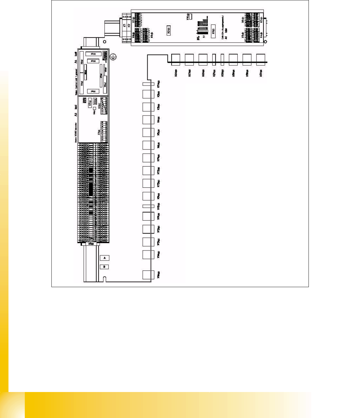
4.2.2 Main distribution Unit, section 2
Fig. 4.2 - 1 section 2, main distributor
Legend:
1. Terminal block X1qa (GND, +3.3V, +5V, +15V, -15V, +24V, +52V, various signals)
2. DC/DC converter for Twin head stationary cameras and PCB camera placement area 2
3. Vision illumination control board for Twin head stationary cameras
4. CAN bus I/O module (SLIO)
5. Connector bar (connector X2qa - X16qa, X74qa)
52
3
1
4
1 - 9
Student Guide SIPLACE HF/HF3
Edition 09/2005 4 Services to the machine
9
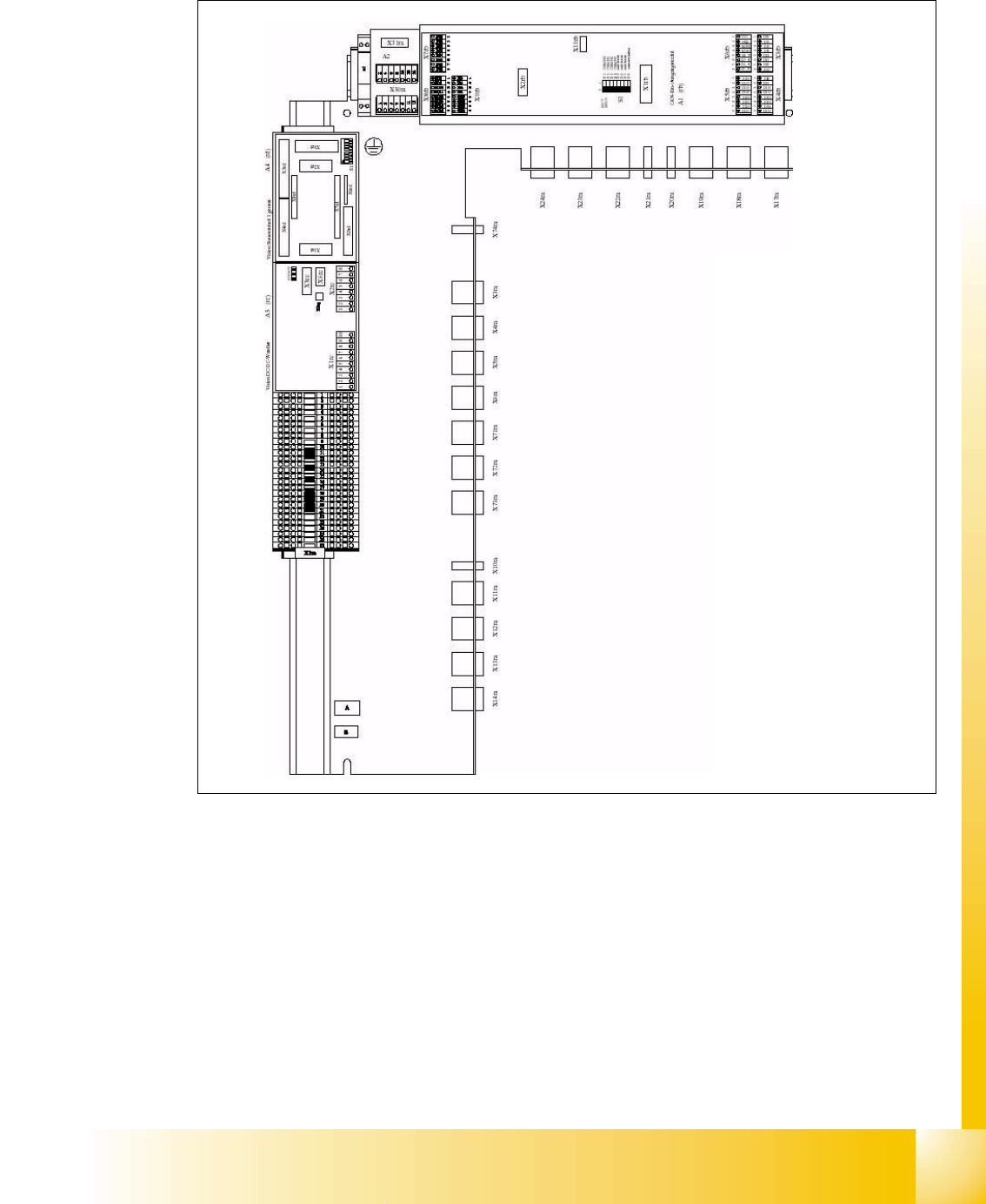
4.2.3 Sub distribution Unit, section 4
Fig. 4.2 - 2 section 4, sub distributor
Legend:
1. Terminal block X1ra ((GND,+5V,+15V,-15V,+24V,+52V, various signals)
2. DC/DC distributor for PCB camera (for stationary cameras future application) on placement
area 1
3. Vision illumination control board for stationary cameras placement area 1 (future application).
4. CAN I/O module (SLIO)
5. Connector bar (connector X3ra - X6ra, X10ra- X14ra, X71ra-X74ra)
52
3
1
4
1 - 10
Student Guide SIPLACE HF/HF3
4 Services to the machine Edition 09/2005
10
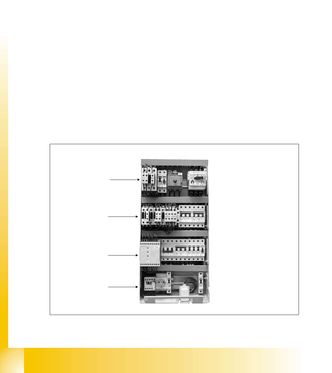
4.2.4 Power Supply Unit
The main power supply unit is mounted on a compact slide-in module, and located on the left
side of the middle section. When viewed from the outside only the red main power switch is visi-
ble.
A lockable door prevents access to the unit.
With the open cover, the state of the following protective devices can be quite easily monitored.
– Motor circuit breaker
– Main contactor
–Safety relay
– Power circuit breaker
With the lockable door open, the state of all circuit breaker, contactor and the condition of the
safety combination (SSK) can be easily monitored
to access the power supply for country specific installment:
1. Unlock the interlock device
2. Slide out the module
3. Reconfigure for country specific power
r
Fig. 4.2 - 3 main power unit
SSK
K5
K2, K3, K4
K1