SG_FSE_SiplaceHF_HF3_00193901-05_eng.pdf - 第126页
1 - 12 S tudent Guide SIPLACE HF/HF3 4 Services to the machine Edition 09/2005 12 Fig. 4.2 - 4 main power supply unit Legend F7 fuse secundary circuit; 3-phase 1, 3, 5 u. 2, 4, 6 3 x 230 V AC F8 fuse PCB-transport; 1-pha…

1 - 11
Student Guide SIPLACE HF/HF3
Edition 09/2005 4 Services to the machine
11
For operating the SIPLACE HF, a 3 phase alternating power is supplied. ’N’ is only used for the
service socket. The contacts L1/L2/L3/N/PE are below the main power module. The separate pro-
tected Fuse F1 is crotched before the power filter (1 phase).
Units Identification Contact Voltages
X100 main power supply L1, L2, L3 3 x 204 VAC / 3 x 380 VAC
3 x 400 VAC / 3 x 415 VAC
X102 service socket 115 VAC / 220 VAC / 230 VAC / 240 VAC
Q1 main switch 1, 3, 5 u.
2, 4, 6
3 x 204 VAC / 3 x 380 VAC
3 x 400 VAC / 3 x 415 VAC
Q2 motor circuit breaker 1, 3, 5 u.
2, 4, 6
3 x 204 VAC / 3 x 380 VAC
3 x 400 VAC / 3 x 415 VAC
K1 main contactor 1, 3, 5 u.
2, 4, 6
3 x 204 VAC / 3 x 380 VAC
3 x 400 VAC / 3 x 415 VAC
K2 contactor 1, 3, 5 u.
2, 4, 6
3 x 177 VAC
K3 contactor 1, 3, 5 u.
2, 4, 6
3 x 177 VAC
K4 contactor 1, 3, 5 u.
2, 4, 6
3 x 177 VAC
K5 contactor A1(+)– A2 (-)
1,2
3,4
5,6
24VDC
24 VDC to GND
24 VDC to GND
24 VDC to GND
K6 (SSK) safety combination L+, X3, X5 24 VDC to GND
F1 fuse service socket;
1-pol.
1, 2 115 VAC / 220 VAC
230 VAC / 240 VAC
F2 fuse co-table;
3-pol.
1, 3, 5 u.
2, 4, 6
3 x 36 VAC
F4 fuse X- / Y-axis;
3-phase.
1, 3, 5 u.
2, 4, 6
3 x 177 VAC
F5 fuse star-axis;
1-phase
1, 2 145 VDC to GND
F6 fuse Z- and DP-axis;
1-phase.
1, 2 39 VDC to GND
1 - 12
Student Guide SIPLACE HF/HF3
4 Services to the machine Edition 09/2005
12
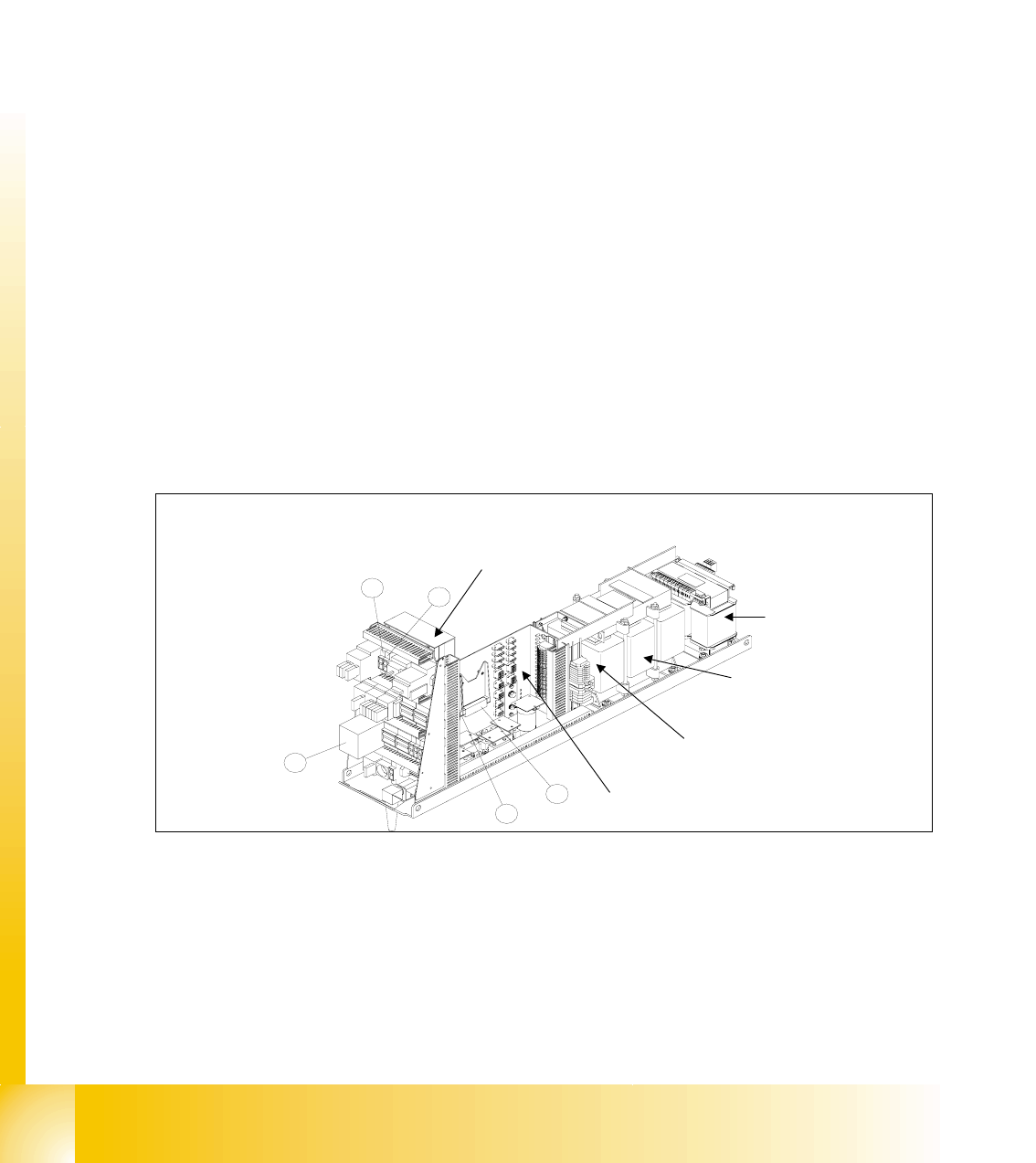
Fig. 4.2 - 4 main power supply unit
Legend
F7 fuse secundary circuit;
3-phase
1, 3, 5 u.
2, 4, 6
3 x 230 VAC
F8 fuse PCB-transport;
1-phase
1, 2 33 VDC to GND
F10 fuse rectifier V7 and V70;
3-phase
1, 3, 5 u.
2, 4, 6
3 x 39 VAC
F11 fuse inrush current limiter
1-phase
1, 2 33,6 VDC to GND
F12 fuse illumination
1-pol.
1, 2 52 VDC to GND
F13 fuse monitor;
1-pol.
1, 2 26 VDC to GND
F14 fuse Y-motor cooling device
1-phase
1, 2 26 VDC to GND
F61 / F62 fuse rectifier V4 3 x 28 VAC
F81 / F82 fuse rectifier V5 3 x 23,8 VAC
F111 / F112 fuse rectifier V8 3 x 23,8 VAC
F131 / F132 fuse rectifier V10 3 x 19,7 VAC
F141 / F142 fuse rectifier V11 3 x 18,7 VAC
(1) DC / DC Converter 24 V (4) Fuse F11 for inrush current limiter
(2) DC / DC Converter 5 V (HF)and 24V (HF3) (5) Fuse F6 for star axis
(3) Safety combination relay K6
1
2
3
4
5
main distributor main
power supply
Inrush current limiter:
a: transformer: EST
b: servo: Ess
transformer T2
transformer T1
T1
T2
Fuse F61 - fuse F142
1 - 13
Student Guide SIPLACE HF/HF3
Edition 09/2005 4 Services to the machine
13
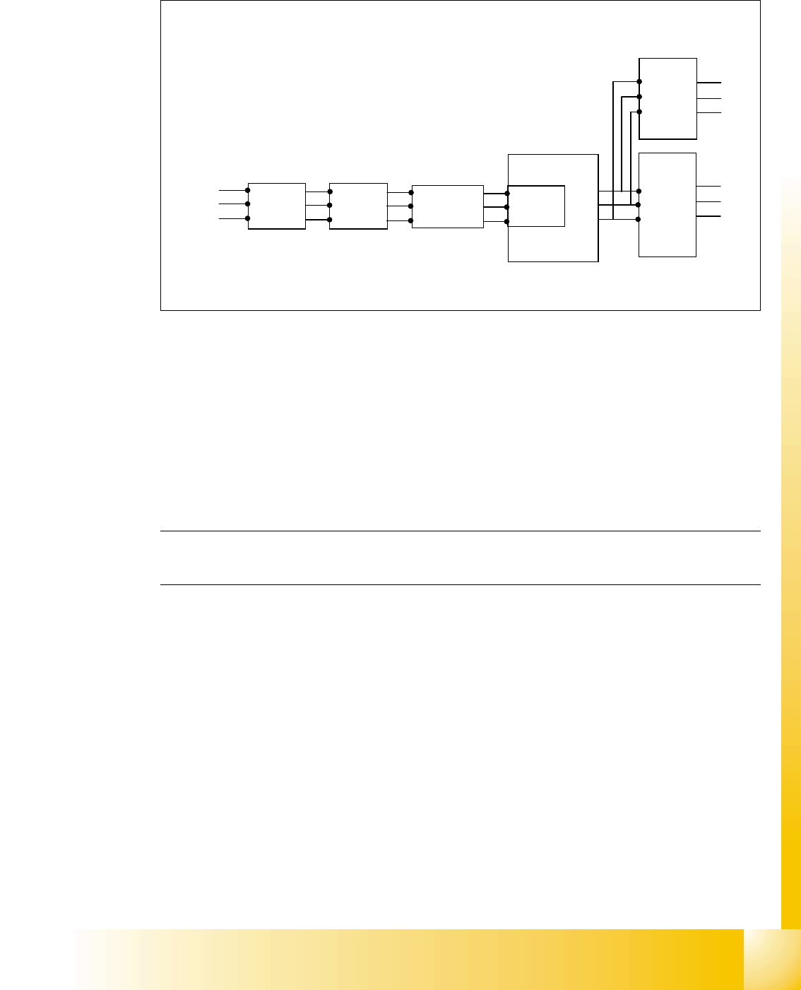
4.2.4.1 Input Voltage
Fig. 4.2 - 5 input voltage
Legend
Q1: main switch
Q2: motor circuit breaker
K1: main contactor and inrush current limiter for T1
T1: transformer 1
T2: transformer 2
Please Note: After the transformer T1 and T2, the main power potential end and only secundary
voltages supply the machine
Q1
Q2
K1
3 phase
U
V
W
T1
U
V
W
T2
3x 230 V
Ínrush current
limiter for T1
L1
L2
L3
power
filter