SG_FSE_SiplaceHF_HF3_00193901-05_eng.pdf - 第132页
1 - 18 S tudent Guide SIPLACE HF/HF3 4 Services to the machine Edition 09/2005 18 4.2.5 Power Supply Computer Unit When the main switch is on, th e DC/DC converter in the computer unit is supplied with 52 VDC by the main…
1 - 17
Student Guide SIPLACE HF/HF3
Edition 09/2005 4 Services to the machine
17
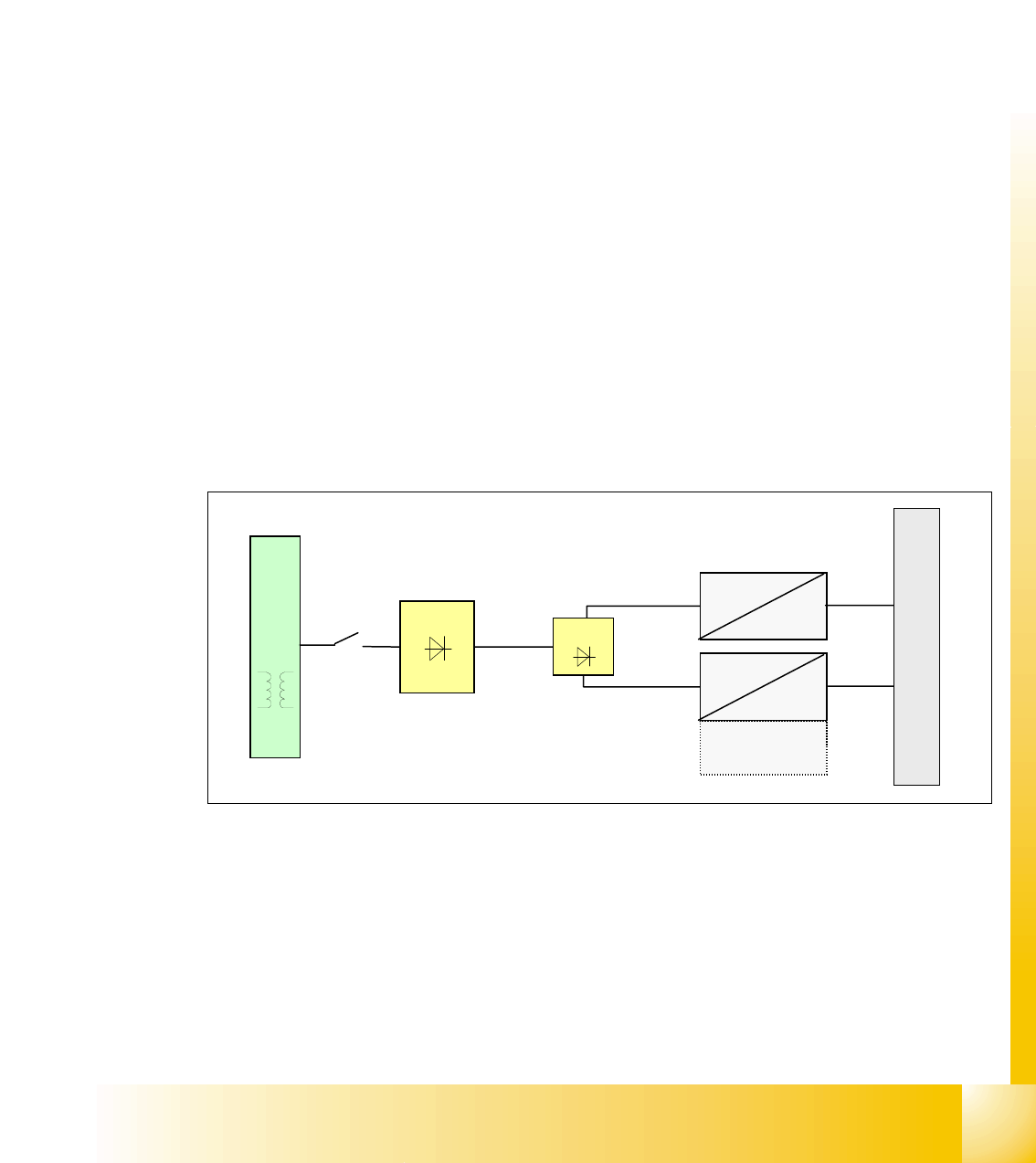
4.2.4.5 DC/DC Converter in Main Power Supply
Two DC/DC converter U20 and U30 generate the 24 VDC and 5 VDC, which are used overall in
the electrical system, are located in the main power supply module.
DC/DC converter U20:
1.+24 VDC converted from 52 VDC is split into 4 path
– path 1: power for servo enable
– path 2: SSK relay K6
– path 3: for inrush current limiter servo
– path 4: mainly used: general use of 24V all over the machine
2.+24 VDC converted from 52 VDC is split into 2 path only on the HF3 machine:
– ventilator for the axis unit
– PCB transport control board
DC/DC converter U30:
5 VDC logic power, which his mainly used in the overall machine
Fig. 4.2 - 8 DC/DC converter main power supply
T1
U7
52 VDC
24 VDC
52 VDC
5 VDC
U6
F10
main power supply distributor
24 VDC for
HF3
1 - 18
Student Guide SIPLACE HF/HF3
4 Services to the machine Edition 09/2005
18
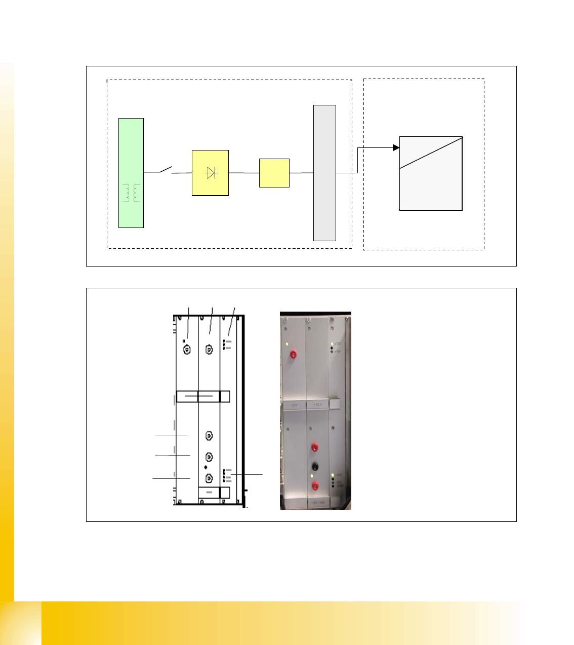
4.2.5 Power Supply Computer Unit
When the main switch is on, the DC/DC converter in the computer unit is supplied with 52 VDC
by the main power supply unit. The following voltages are then generated in the control unit:
4
+ 3.3 VDC / 6A to supply the CPU of Machine Controller and CPU of Station Computer. 4
+ 5 VDC / 6A to supply the digital electronic circuits. 4
± 12 VDC to supply the digital electronic circuits. 4
± 15 VDC (not used, LED off) 4
4
4
Fig. 4.2 - 9 DC/DC converter computer unit
power supply
52 VDC
5 VDC
52 VDC
+ 3.3 V
+ 5V/6A
+- 12V
+- 15V
GND
U6
T1
U7
F10
power supply main distributor
computer unit
not used: +- 15V
123
4
5
6
7
1. power 3.3 V (CPU)
2. not used
3. LED +12 V (ON) and +15 V (OFF)
4. power +52 V
5. GND
6. power 5 VDC, 6A
7. LED -12 VDC, GND, -15 VD
1 - 19
Student Guide SIPLACE HF/HF3
Edition 09/2005 4 Services to the machine
19
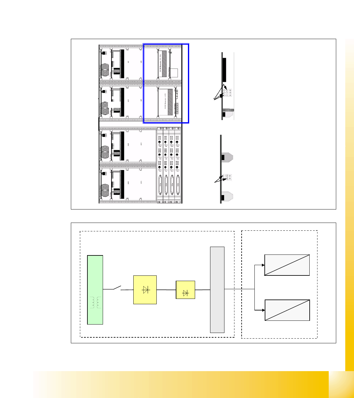
4.2.6 Power Supply Axis Unit
When the main switch is on, the axis unit is supplied with 52 V from main power supply via X13
and generates the voltages as shown below.
The +-15V and 5V supply voltages for the servo unit’s electronic circuits are generated from the
two DC/DC converter, which are integrated in the servo unit. This DC/DC converter generates the
5V and +- 15V needed for the servo board and the axis controller and the +-15V are also used on
placement heads and anti-crash, for e.g. It will travel to main distributor X4qa (sector 2) and then
to terminal block X1qa and get distributed from here.
4
4
4
Fig. 4.2 - 10 DC/DC converter axis unit
1
2
o
o
power supply on top: +-15 / 5V
o
o
o
1
+5V Axis controller
+15V Servo
-15V Servo
GND
2
-15V axis controller and machine
+15V axis controller and machine
power supply bottom: +-15 V
GND
GND
power supply
52 VDC
5 VDC
U6
T1
U7
F10
main power supply distributor
52 VDC
+5 VDC
+- 15 VDC
52 VDC
+-15 VDC
2
1
axis unit