SG_FSE_SiplaceHF_HF3_00193901-05_eng.pdf - 第136页
1 - 22 S tudent Guide SIPLACE HF/HF3 4 Services to the machine Edition 09/2005 22 4.2.8.2 Control loop Component T able Loop 4 The 4 component tab les are s witched in parallel mode. If 1 or more tab le is not connetcted…
1 - 21
Student Guide SIPLACE HF/HF3
Edition 09/2005 4 Services to the machine
21
4.2.8 Safety and Control Loop(HF/HF3 bis MA.Nr. xx)
Please Note: For machine type A you consult the enclosed circuit diagrams.
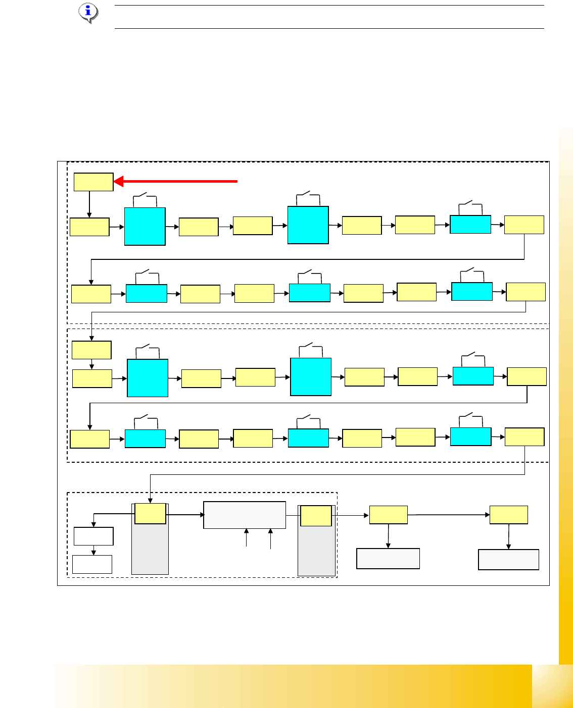
4.2.8.1 Émergency Stop Loop (safety loop)
Following contacts are switched in serial and build the safety loop: _ 4
– 4 protective cover switches (main cover).
– conveyor cover switch.
– contact on component change over table
– emergency stop button must be released
Fig. 4.2 - 13 safety loop
If the emergency stop loop is closed, 24 V will be present on K5, contact 3. Another 24 V signal
travels to each CAN I/O module as
’emergency stop loop OK’ and signalize that all covers are
closed and table connected.
security loop START
sub distributor section 4
main distributor section 2
24 V
X1ra
input
conv.
left
X11ra
X11ra
input
conv.
right
X12ra
X12ra
cover 1
X13ra
X13ra
cover 4
X14ra
X14ra
table 1
X18ra
X18ra
table 4
X23ra
X23ra
X72qa
output
conv.
right
X11qa
X11qa
output
conv.
left
X12qa
X12qa
cover 2
X13qa
X13qa
cover 3
X14qa
X14qa
table 2
X18qa
X18qa
table 3
X23qa
X23qa
X16
K5
CAN I/O
CAN I/O
X2qa
X73qa
section 2
section 4
24 V
power supply
SSK
24 V
24 V
24 V
electrical isolation
(optical coupler)
GND
input
input
X16
&
d
i
s
t
i
b
u
t
o
r
d
i
s
t
i
b
u
t
o
r
1 - 22
Student Guide SIPLACE HF/HF3
4 Services to the machine Edition 09/2005
22
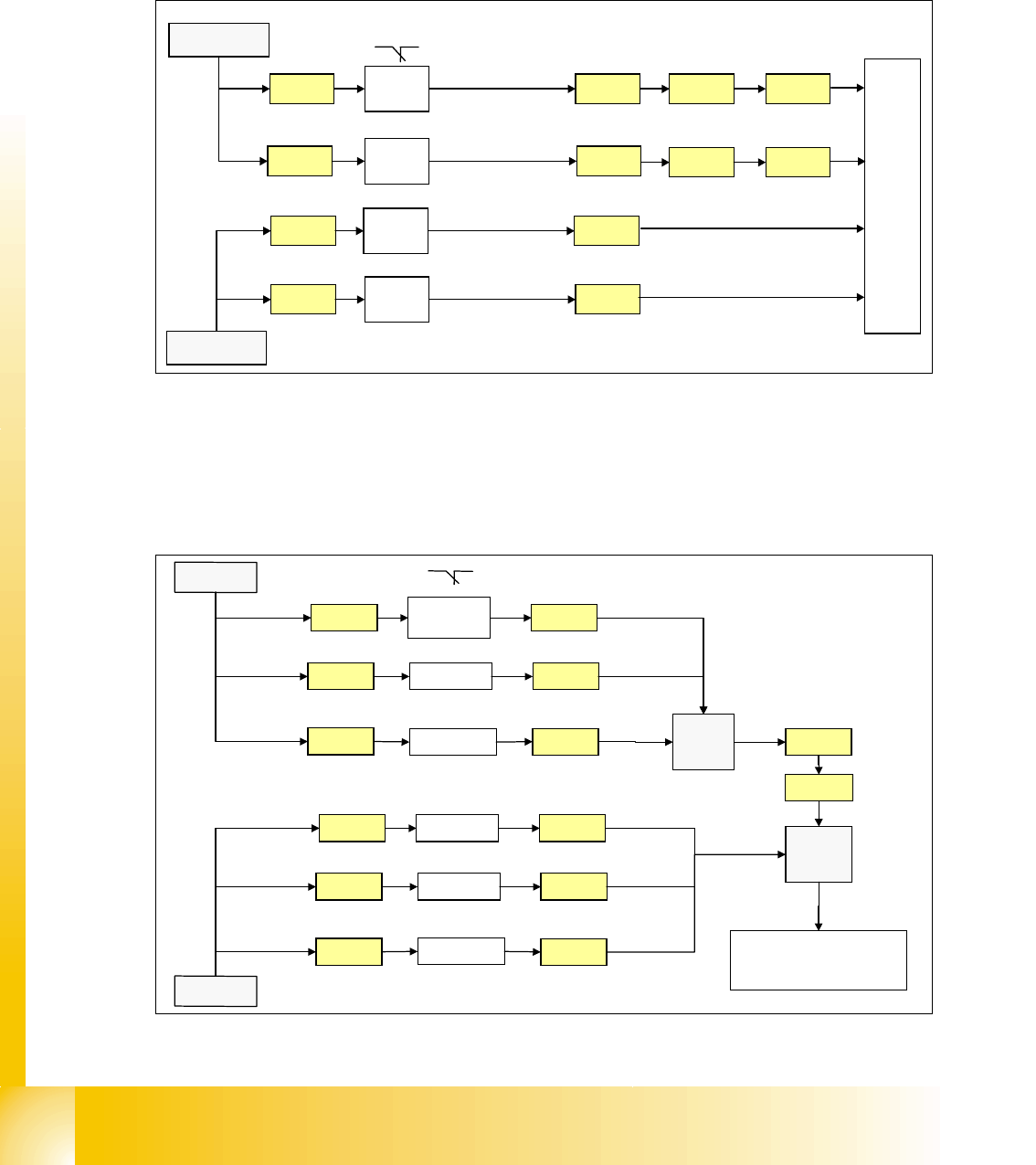
4.2.8.2 Control loop
Component Table Loop 4
The 4 component tables are switched in parallel mode. If 1 or more table is not connetcted, the
contact is closed and the 24V signal is set on the CAN I/O module in section 2 and shows which
component table is not connected.
Fig. 4.2 - 14 component table loop
Cover control Loop 4
The cover control loop consists of 6 contacts (4 cover and 2 transport) and they are switched in
parallel mode. If 1 ore more cover is open, the contact is closed and the 24 V signal sets an input
on CAN I/O module in section 4 and shows, that any cover is open.
.
Fig. 4.2 - 15 cover control loop
24V
X18ra
Co-
table 1
M_co-table 1
C
A
N
I
/
O
m
o
d
u
l
e
s
e
c
t
i
o
n
2
X23ra
Co-
table 4
X23qa
Co-
table 3
M_co-table 3
X73ra X73qa
X73ra X73qa
X18qa
Co-
table 2
M_co-table 2
X18ra
X23ra
X23qa
X18qa
X1ra
24V
24V
24V
M_co-table 4
X1qa
input
24V
Cover 3 X1qa
X14qa
X
1
q
a
24V
X73qa
X73ra
Cover 2X13qa
24V
X13qa
X14qa
PCB
output
X11qa X11qa
X1ra
C
A
N
I
/
O
m
o
d
u
l
e
s
e
c
t
i
o
n
4
24V
Cover 4
X14ra
X
1
r
a
24V
24V
Cover 1X13ra
24V
X13ra
X14ra
PCB inputX11ra X11ra
24V
input
1 - 23
Student Guide SIPLACE HF/HF3
Edition 09/2005 4 Services to the machine
23
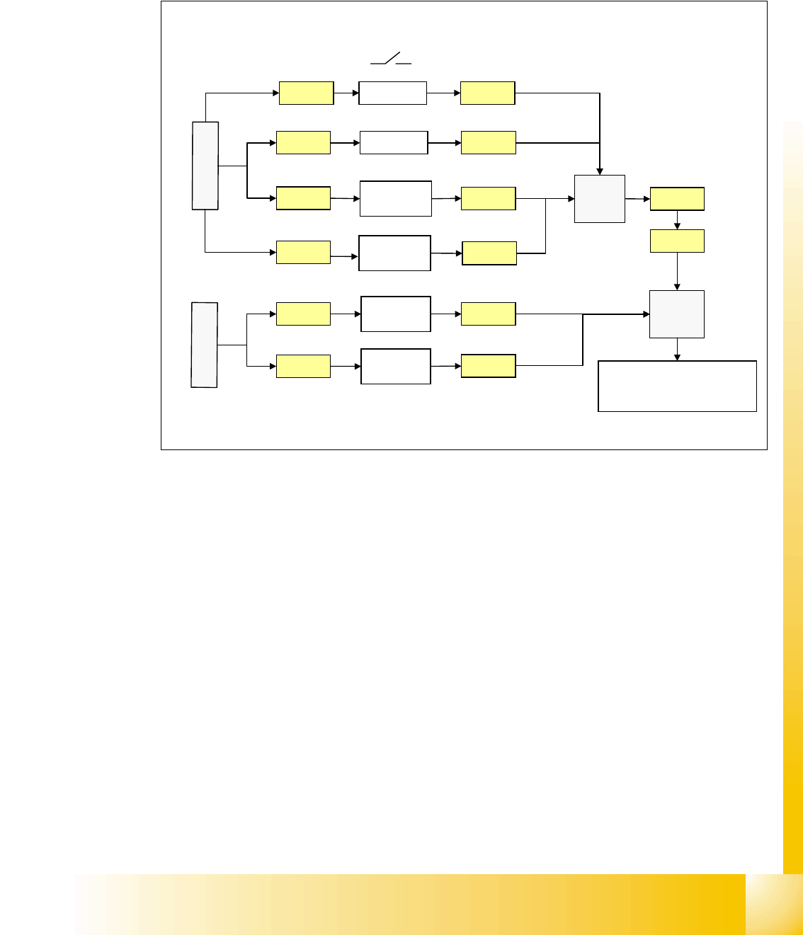
Stop Button Loop 4
The stop button loop consists of 6 contacts which are switched in parallel mode.
If 1 ore more stop button is pressed, the contact is closed and the 24 V signal sets an input on
CAN I/O module in section 4 and shows, that any stop button is pressed.
Fig. 4.2 - 16 stop button loop
24V
Stop PCB
out right
Stop PCB
out left
X1qa
Stop PCB
in right
X11qa
X12qa
X11ra
X
1
q
a
24V
24V
X73qa
X73ra
Stop rightX10qa
24V
Stop PCB
in left
X12ra
X
1
r
a
X10qa
X11qa
X12qa
X11ra
X12ra
Stop leftX9qa X9qa
X1ra
C
A
N
I
/
O
m
o
d
u
l
e
s
e
c
t
i
o
n
4
input
3
4