SG_FSE_SiplaceHF_HF3_00193901-05_eng.pdf - 第137页
1 - 23 S tudent Guide SIPLACE HF/HF3 Edition 09/2005 4 Servic es to the machine 23 Stop Butto n Loop 4 The stop bu tton loop consists of 6 cont acts which are switch ed in parallel mode. If 1 ore more stop button is pres…
1 - 22
Student Guide SIPLACE HF/HF3
4 Services to the machine Edition 09/2005
22
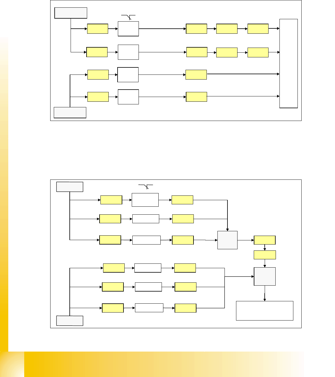
4.2.8.2 Control loop
Component Table Loop 4
The 4 component tables are switched in parallel mode. If 1 or more table is not connetcted, the
contact is closed and the 24V signal is set on the CAN I/O module in section 2 and shows which
component table is not connected.
Fig. 4.2 - 14 component table loop
Cover control Loop 4
The cover control loop consists of 6 contacts (4 cover and 2 transport) and they are switched in
parallel mode. If 1 ore more cover is open, the contact is closed and the 24 V signal sets an input
on CAN I/O module in section 4 and shows, that any cover is open.
.
Fig. 4.2 - 15 cover control loop
24V
X18ra
Co-
table 1
M_co-table 1
C
A
N
I
/
O
m
o
d
u
l
e
s
e
c
t
i
o
n
2
X23ra
Co-
table 4
X23qa
Co-
table 3
M_co-table 3
X73ra X73qa
X73ra X73qa
X18qa
Co-
table 2
M_co-table 2
X18ra
X23ra
X23qa
X18qa
X1ra
24V
24V
24V
M_co-table 4
X1qa
input
24V
Cover 3 X1qa
X14qa
X
1
q
a
24V
X73qa
X73ra
Cover 2X13qa
24V
X13qa
X14qa
PCB
output
X11qa X11qa
X1ra
C
A
N
I
/
O
m
o
d
u
l
e
s
e
c
t
i
o
n
4
24V
Cover 4
X14ra
X
1
r
a
24V
24V
Cover 1X13ra
24V
X13ra
X14ra
PCB inputX11ra X11ra
24V
input
1 - 23
Student Guide SIPLACE HF/HF3
Edition 09/2005 4 Services to the machine
23
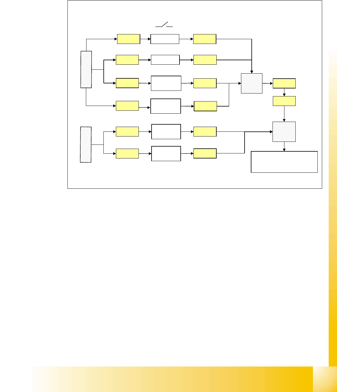
Stop Button Loop 4
The stop button loop consists of 6 contacts which are switched in parallel mode.
If 1 ore more stop button is pressed, the contact is closed and the 24 V signal sets an input on
CAN I/O module in section 4 and shows, that any stop button is pressed.
Fig. 4.2 - 16 stop button loop
24V
Stop PCB
out right
Stop PCB
out left
X1qa
Stop PCB
in right
X11qa
X12qa
X11ra
X
1
q
a
24V
24V
X73qa
X73ra
Stop rightX10qa
24V
Stop PCB
in left
X12ra
X
1
r
a
X10qa
X11qa
X12qa
X11ra
X12ra
Stop leftX9qa X9qa
X1ra
C
A
N
I
/
O
m
o
d
u
l
e
s
e
c
t
i
o
n
4
input
3
4
1 - 24
Student Guide SIPLACE HF/HF3
4 Services to the machine Edition 09/2005
24
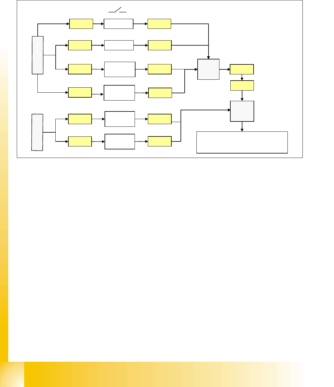
Start Button Loop 4
The start button loop consists of 6 contacts and they are switched in parallel mode.
If 1 ore more start button is pressed, the contact is closed and the 24 V signal sets an input on
CAN I/O module in section 4 and shows, that any start button is pressed.
Fig. 4.2 - 17 start button loop
4.2.8.3 How does the emergency stop loop work?
The placement system cannot be used in placement mode until all the supply voltages have been
enabled by the protective circuit. The following conditions must also be fulfilled:
4
– All four component change-over tables must be docked.
– All covers must be closed.
– Both emergency stop push-buttons must be released.
– The minimum air pressure must be present.
– The software enable signal must be ready.
– The Message ’
Security Loop OK’ must be sent (for GND on X6 on SSK, CAN I/O output)
– 24 V must be present at the start button.
After the start button is pressed, the SSK combinaton activates the following voltages
: _ 4
– secundary circuit 250 V for servo X/Y axis (via K2, K3, K4).
– secundary circuit 150 V for star axis.
– servo unit receives ’Servo Enable’ signal for servo amplifier (K4.5)
24V
Start PCB
out right
Start PCB
out left
Start PCB
in right
X11qa
X12qa
X11ra
X
1
q
a
24V
24V
Start rightX10qa
24V
Start PCB
in left
X12ra
X
1
r
a
X10qa
X11qa
X12qa
X11ra
X12ra
Start leftX9qa X9qa
X1ra
X1qa X73qa
X73ra
CA
N
I
/
O
m
o
d
u
l
e
s
e
c
t
i
o
n
4
input
3
4