SG_FSE_SiplaceHF_HF3_00193901-05_eng.pdf - 第139页
1 - 25 S tudent Guide SIPLACE HF/HF3 Edition 09/2005 4 Servic es to the machine 25 – The messag e ’Ctrl_On ’ must be sent to CA N I/O (24V fr om axis unit after receiving th e ’servo enable) – 34 V operating voltage for …
1 - 24
Student Guide SIPLACE HF/HF3
4 Services to the machine Edition 09/2005
24
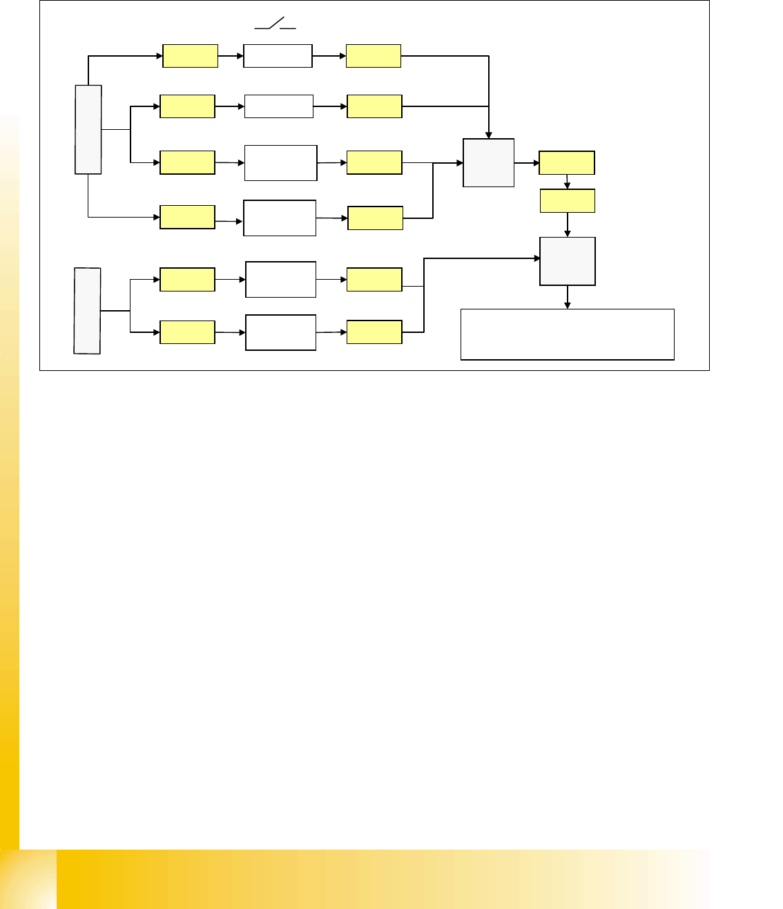
Start Button Loop 4
The start button loop consists of 6 contacts and they are switched in parallel mode.
If 1 ore more start button is pressed, the contact is closed and the 24 V signal sets an input on
CAN I/O module in section 4 and shows, that any start button is pressed.
Fig. 4.2 - 17 start button loop
4.2.8.3 How does the emergency stop loop work?
The placement system cannot be used in placement mode until all the supply voltages have been
enabled by the protective circuit. The following conditions must also be fulfilled:
4
– All four component change-over tables must be docked.
– All covers must be closed.
– Both emergency stop push-buttons must be released.
– The minimum air pressure must be present.
– The software enable signal must be ready.
– The Message ’
Security Loop OK’ must be sent (for GND on X6 on SSK, CAN I/O output)
– 24 V must be present at the start button.
After the start button is pressed, the SSK combinaton activates the following voltages
: _ 4
– secundary circuit 250 V for servo X/Y axis (via K2, K3, K4).
– secundary circuit 150 V for star axis.
– servo unit receives ’Servo Enable’ signal for servo amplifier (K4.5)
24V
Start PCB
out right
Start PCB
out left
Start PCB
in right
X11qa
X12qa
X11ra
X
1
q
a
24V
24V
Start rightX10qa
24V
Start PCB
in left
X12ra
X
1
r
a
X10qa
X11qa
X12qa
X11ra
X12ra
Start leftX9qa X9qa
X1ra
X1qa X73qa
X73ra
CA
N
I
/
O
m
o
d
u
l
e
s
e
c
t
i
o
n
4
input
3
4
1 - 25
Student Guide SIPLACE HF/HF3
Edition 09/2005 4 Services to the machine
25
– The message ’Ctrl_On’ must be sent to CAN I/O (24V from axis unit after receiving the
’servo enable)
– 34 V operating voltage for the transport handling.
– 24 V operating voltage for the tape cutter.
– M_X/Y: 24 V+ for K3 and K4
– M_tape cutter: 24 V+ for K2
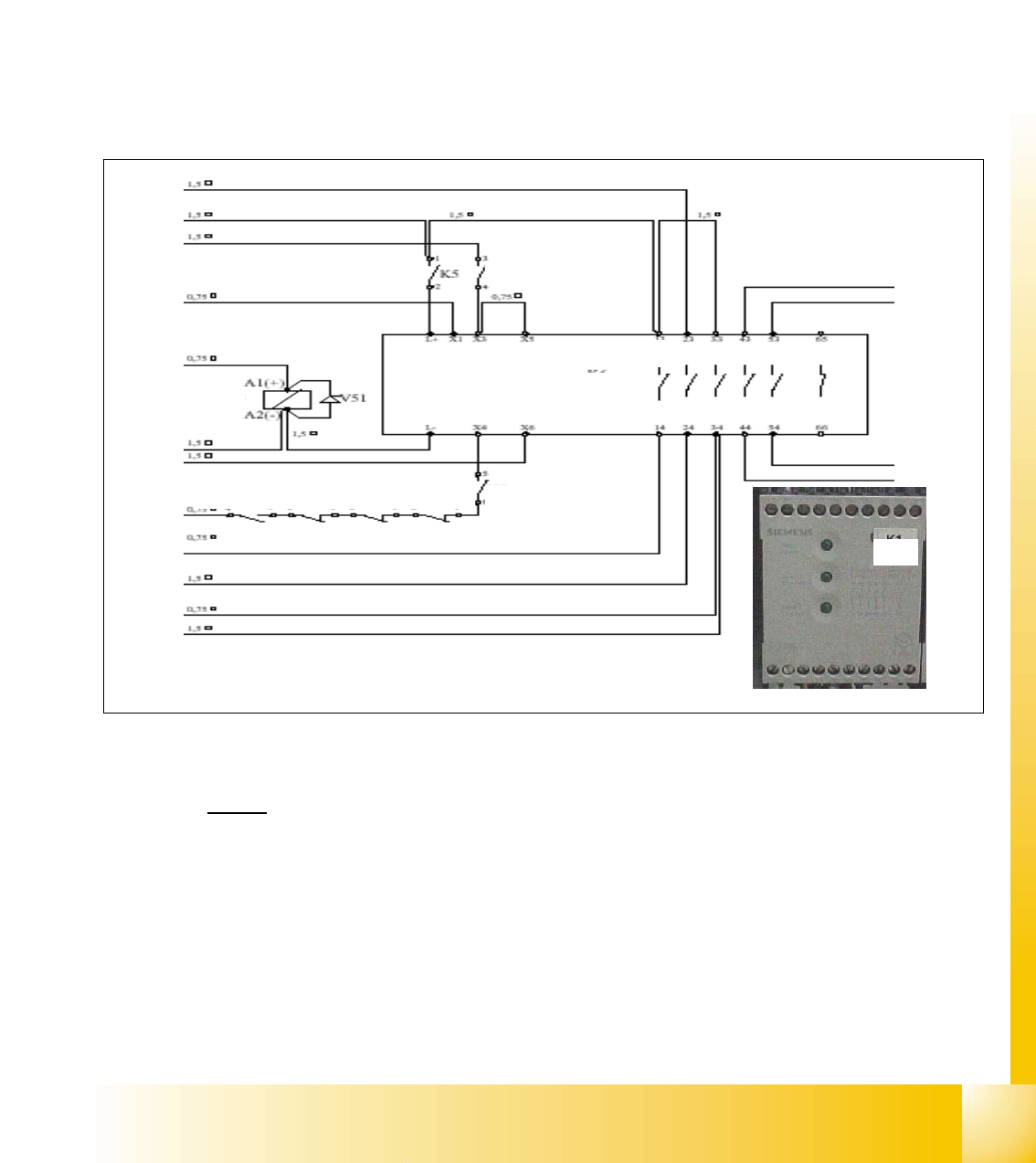
4.2.9 The Safety Combination (K6 Relay)
Legend
top row
1. power for transport 34 VDC from T2
2. power 24 VDC input from power supply DC/DC converter.
3. input from emergency stop loop (24 VDC)
4. message ready to SLIO (SSK is fine).
5. software release (24 VDC when start button pressed and SW release signal is given).
L+ X1 X3 X5 X7 X9 X11
L- X2 X4 X6 X8 X10
1
2
3
4
5
6
7
8
9
10
auxillary contact
K1.4 K2.4 K3.4 K4.4
K5
SSK K6
power / channel 1 / channel 2
H1 ⊗ H2 ⊗ H3 ⊗
SSK 43
SSK 53
SSK 54
SSK 44
K5K5
K5
K6

1 - 26
Student Guide SIPLACE HF/HF3
4 Services to the machine Edition 09/2005
26
bottom row
6. GND for SSK (X6), from Message ’security loop OK’
7. start button pressed (24 VDC form start button).
8. M_X/Y: 24 VDC from SSK (power for K3 and K4).
9. power for transport 34 VDC from SSK
10. M_tape cutter: 24 VDC for contactor K2 and power for tape cutter (24 VDC)
About SSK K6
Contactor K6 is an industry standard safety combination contactor. Internally it consists of 3 relays
which are configured in a complex fashion to give maximum protection in a fail safe mode. Unfor-
tunately, for ease of understanding, these internal relays are labeled K1', K2' & K3'. The status of
the contactor is indicated by LEDs labeled as H1, H2 and H3.
When the contactor is in an energized state internal relays K2' and K3' are energized, relay K1' is
de-energized. This status closes the contacts 13 and 14, 23 and 24, 33 and 34.
IWhen this status is achieved K6 can be said to be ‚ON' and the 3 LEDs H1, H2 and H3 are all lit.
How is SSK K6 energized?
If the safety covers are closed, the emergency stop circuit intact and K5 closed, 24 V is supplied
to terminal X1, X3 and X4, when GND is given on contact 6 (X6) from Message ’security loop OK’
and when a start button is pressed. This voltage allows K1' to be energized and when it's contacts
close then K2' and K3' can energize. As soon as these relays energize, K1' is de-nergized how-
ever K2' and K3' now remain energized due to their contacts providing a self latching facility.
Pressing the ON Button
Assuming any ON button is pressed: 24 V will travel and will split into 2 path.
– 1st path: It will travel to the CAN I/O module 1. The signal from this module will travel from
the CAN bus to notify the Machine Controller that ON button is pressed; this should disable
the Press Start Key message.
– 2nd path: It will travel to the power supply main distributor X16_2, from here, this signal (On
Button) will travel to K1.4 (closed when main switch On), K2.4 (NC), K3.4 (NC), K4.4 (NC),
K5 (NO) and stop at pin 6 of SSK.
The 24 V will only travel when the following conditions are met:
4
When the machine controller gets the signal (1st path) ’START BUTTON pressed’, it will
through the CAN I/O module set an output and proceed to A1 of contactor K5 to energize
K5 (C_Software_On)
4
So when K5 is energized, the signal from 2nd path will flow to X4 of the SSK. 4