SG_FSE_SiplaceHF_HF3_00193901-05_eng.pdf - 第142页
1 - 28 S tudent Guide SIPLACE HF/HF3 4 Services to the machine Edition 09/2005 28 4.2.10.2 Security Loop OK signal The security loop signal is given by the CAN I/O when following conditions are filled. Emergency stop loo…
1 - 27
Student Guide SIPLACE HF/HF3
Edition 09/2005 4 Services to the machine
27
4.2.9.1 How does the SSK latch?
Condition: When K5 is energized, the following will happen: 4
– L+ will get 24 V and will light up the first LED
– Since L+ and X1 are internally connected, this 24 V signal will be fed back from X1 to the
CAN I/O module as a SSK READY signal to the MC.
– The X4 on SSK will have 24 V temporary (only when ON is pressed), but it is enough to
energize K1' internal of the SSK. When K1’ is energized, K2' and K3' will also be energized
internally of SSK - only if X3 and X5 of SSK has 24 V with them.
How does X3 and X5 of SSK get the 24V?
– If all covers closed, feeder table locked on, E_Stop released - a 24 V will pass as the emer-
gency loop signal to K5 pin 3 and 4. It proceeds then to X3 and X 5 of SSK.
How does X14 and X34 get hte 24 V?
– When K2' and K3' are latched inside the SSK, pin 34 of SSK will have 24 V.
Main task of them is to power the tape cutter and to energize K2.
4
– When K2’ and K3’ are latched inside the SSK, pin 14 of SSK will have 24 V.
Main task of it is to energize K3 and K4 (with a slight delay).
4
4.2.10 Various Signal
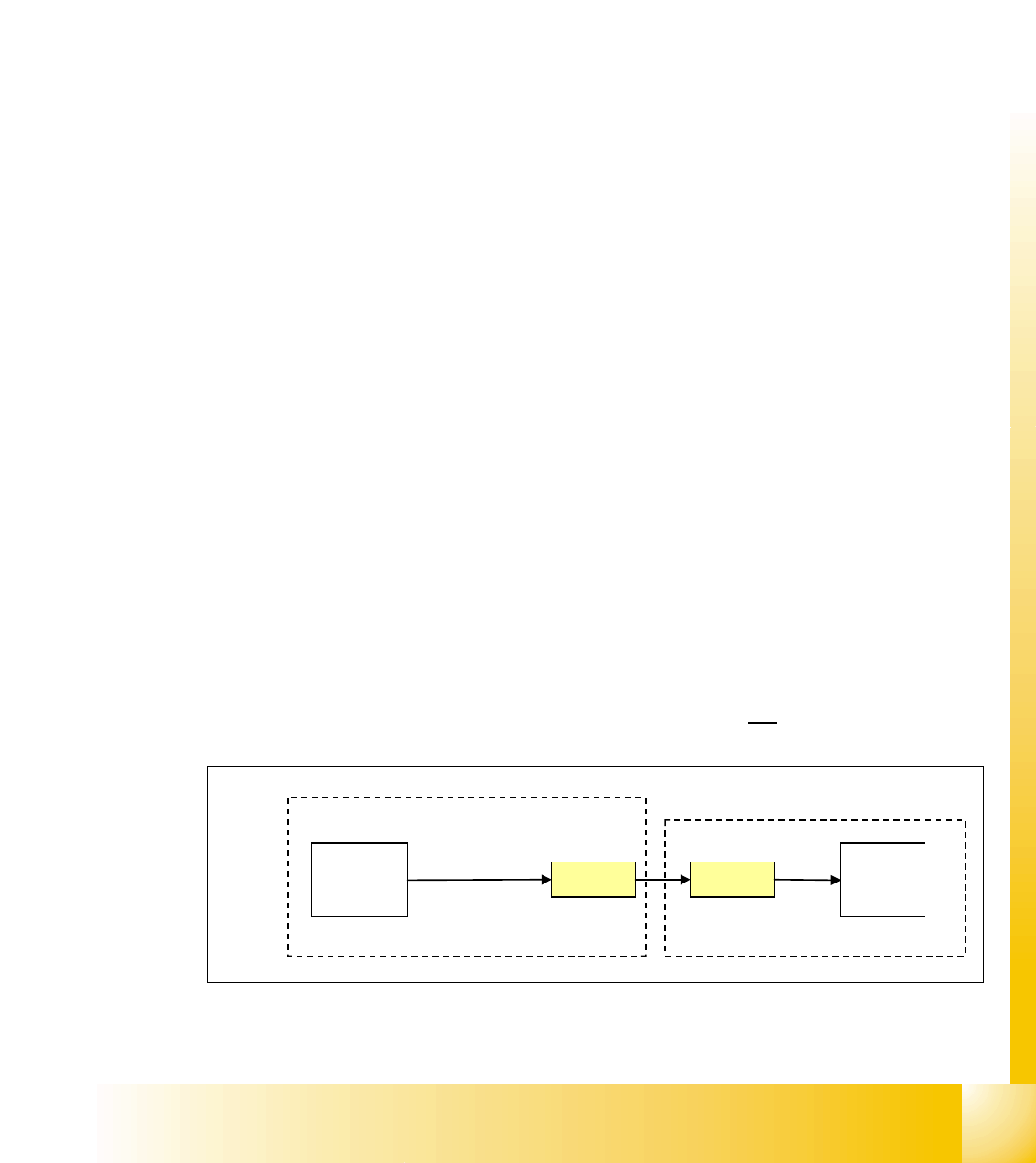
4.2.10.1 Software Release (Software Enabled)
The software release signal is given by the CAN I/O card when the machine controller software is
fully booted. This means that not only must the machine controller software be booted but com-
munication must be established to the vision system, axis cards, CAN BUS, station computer and
line computer (unless it is operating in stand-alone mode).
The software release signal is only present on K5, contact A1 when the CAN I/O gives the signal
in combination when the start button is pressed.
If the emergency stop circuit is broken then the software release is
not given.
Fig. 4.2 - 18 software release signal
X2qa
CAN I/O
24 V
X16
K5
contact
A1
power supply
M_software
release
section 2
output
1 - 28
Student Guide SIPLACE HF/HF3
4 Services to the machine Edition 09/2005
28
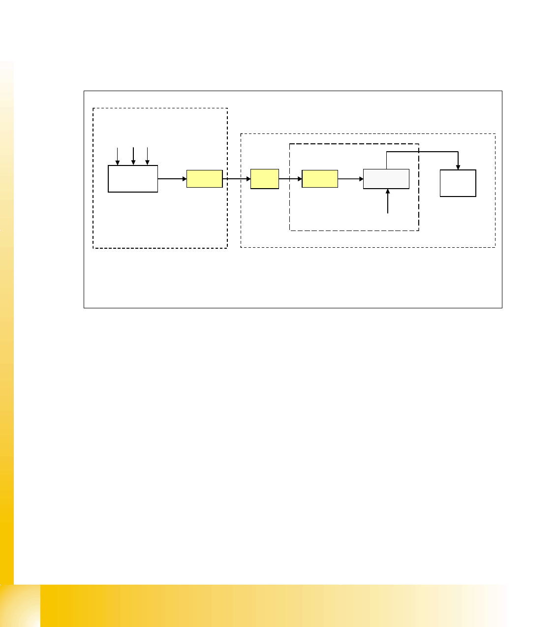
4.2.10.2 Security Loop OK signal
The security loop signal is given by the CAN I/O when following conditions are filled.
Emergency stop loop is closed and in addition, every single safety device send a message to the
CAN I/O module. Inside this module, they are logical matched by using a FPGA and the
CAN I/O set an output 24V ’security messages OK’ which travels to the power supply.
Conditions:
– all covers closed
– all component tables connected
– all emergency stop button released
–
Fig. 4.2 - 19 signal security loop
This signal runs into the power supply X-20 and connects GND to SSK, contact X6.
CAN I/O
module
X2qa
X16
24 V
X8-20
BTS 117
SSK
X6
GND
GND
M_ covers closed
M_ tables connected
M_stop button released
power supply
1
Legend:
1: BTS 117 power switch for GND
section 2
output
inrush current limiter board
1 - 29
Student Guide SIPLACE HF/HF3
Edition 09/2005 4 Services to the machine
29
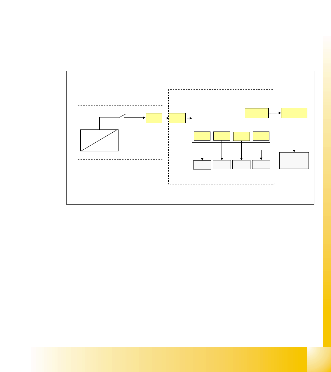
4.2.10.3 Control On signal
With energizing the contactor K4 of power supply, the auxillary contact of K4.5 (K4) get closed.
24 V (servo enable signal) travel from DC/DC converter to main power supply distributor X13 to
axis unit X21 and to Anti-Crash board.
Here it is split in 2 path:
path1: 24 V travel as the
’servo enable signal’ from anti crash board to the servo board X/Y axis
(via X31, X32, X33, X34) to enable the servo amplifier (switching GND to the servo board via op-
tical coupler).
path 2: 24 V travel as the ’
Ctrl_On’ signal to section 2, connector X4qa and end on the CAN I/O
module as
M_Ctrl_On.
The 4 main axis is allowed to move now into any position.
Fig. 4.2 - 20 Control On signal
X21
X39wo
X4qa
CAN I/O
section 2
axis unit
anti crash
board
power supply
X13
DC/DC
U20
K4.5
24V
servo
X31 X32
X33
X34
servo
servo servo
M_Ctrl_On
servo enable
input