SG_FSE_SiplaceHF_HF3_00193901-05_eng.pdf - 第143页
1 - 29 S tudent Guide SIPLACE HF/HF3 Edition 09/2005 4 Servic es to the machine 29 4.2.10.3 Control On signal With energizing the contactor K4 of power supply , the auxillary cont act of K4.5 (K4) get closed. 24 V (servo…
1 - 28
Student Guide SIPLACE HF/HF3
4 Services to the machine Edition 09/2005
28
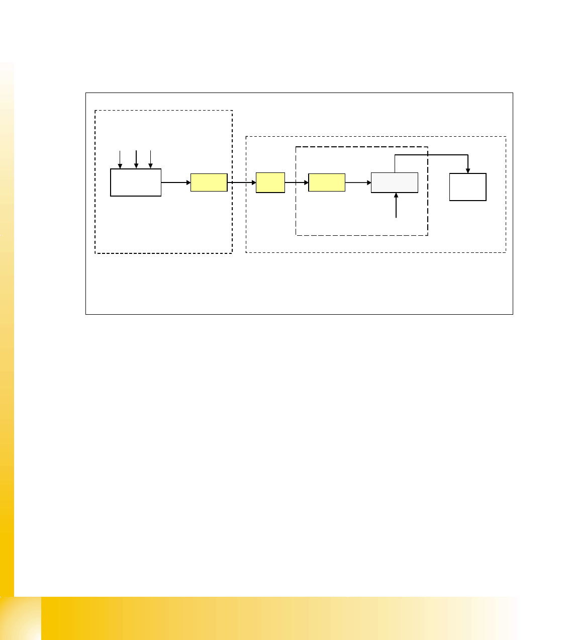
4.2.10.2 Security Loop OK signal
The security loop signal is given by the CAN I/O when following conditions are filled.
Emergency stop loop is closed and in addition, every single safety device send a message to the
CAN I/O module. Inside this module, they are logical matched by using a FPGA and the
CAN I/O set an output 24V ’security messages OK’ which travels to the power supply.
Conditions:
– all covers closed
– all component tables connected
– all emergency stop button released
–
Fig. 4.2 - 19 signal security loop
This signal runs into the power supply X-20 and connects GND to SSK, contact X6.
CAN I/O
module
X2qa
X16
24 V
X8-20
BTS 117
SSK
X6
GND
GND
M_ covers closed
M_ tables connected
M_stop button released
power supply
1
Legend:
1: BTS 117 power switch for GND
section 2
output
inrush current limiter board
1 - 29
Student Guide SIPLACE HF/HF3
Edition 09/2005 4 Services to the machine
29
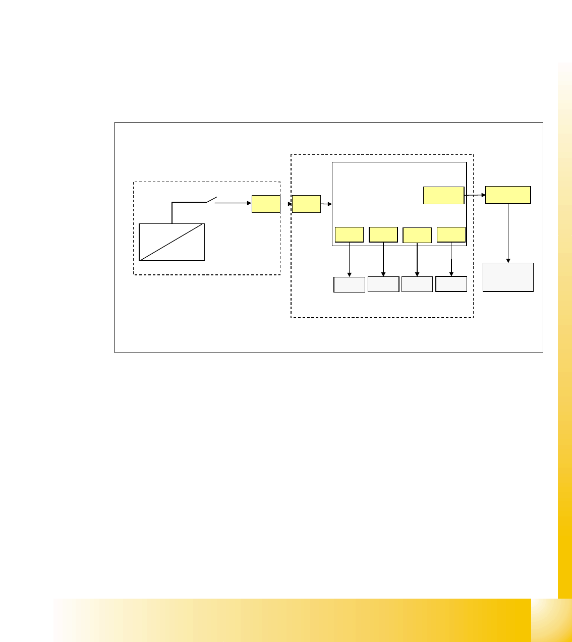
4.2.10.3 Control On signal
With energizing the contactor K4 of power supply, the auxillary contact of K4.5 (K4) get closed.
24 V (servo enable signal) travel from DC/DC converter to main power supply distributor X13 to
axis unit X21 and to Anti-Crash board.
Here it is split in 2 path:
path1: 24 V travel as the
’servo enable signal’ from anti crash board to the servo board X/Y axis
(via X31, X32, X33, X34) to enable the servo amplifier (switching GND to the servo board via op-
tical coupler).
path 2: 24 V travel as the ’
Ctrl_On’ signal to section 2, connector X4qa and end on the CAN I/O
module as
M_Ctrl_On.
The 4 main axis is allowed to move now into any position.
Fig. 4.2 - 20 Control On signal
X21
X39wo
X4qa
CAN I/O
section 2
axis unit
anti crash
board
power supply
X13
DC/DC
U20
K4.5
24V
servo
X31 X32
X33
X34
servo
servo servo
M_Ctrl_On
servo enable
input

1 - 30
Student Guide SIPLACE HF/HF3
4 Services to the machine Edition 09/2005
30
4.2.11 Power Distribution
The power distrubtion to the different section, gantry and heads is highly structured.
5V and 24 V, generated by DC/DC converter U20 and U30 in main power supply, will first travel
to distributor main power supply, connector X16. From here to section 2, main distributor, connec-
tor X2qa and then to the terminal block X1qa for general use and via connector X71qa to section
4, X71ra.
52 V for camera illumination, generated by U7, will travel to main power supply distributor, X18,
and split into two path.
path 1: from X18 to section 2, X3qa, to clamping field X1qa and travel to DC/DC converter vision
for converting the 42 V needed for the IC/FC camera illumination. It travels then also via connector
X71qa to connector X71ra in section 4, to X1ra to DC/DC distributor vision (42V are not used here)
path 2: (this path is presently not shown in overview and not used) from X18 main power supply
distributor to section 4, X3ra, to clamping field X1ra and travel to DC/DC distributor vision for con-
verting the 42 V needed IC/FC camera illumination in this section.
+-15 V are generated in the power supply axis unit from 52 V and travel from here to X4qa to ter-
minal block X1qa to get distributed for general use. It travel then via connector X74qa to X74ra in
section 4 to sub-distributor (not shown in overview ’power distribution’)