SG_FSE_SiplaceHF_HF3_00193901-05_eng.pdf - 第148页
1 - 34 S tudent Guide SIPLACE HF/HF3 4 Services to the machine Edition 09/2005 34 4.3.2 HF Pneumatic System The incoming air supply , specified 5-10 bar passes th rough the filter and is split into 2 main p ath. 1st path…

1 - 33
Student Guide SIPLACE HF/HF3
Edition 09/2005 4 Services to the machine
33
4.3 Pneumatic System
4.3.1 In General
The air is supplied to the vacuum generator, which produces a vacuum using the venturi principle.
The venturi block actually consists of 2 separate venturi nozzles which produce vacuum for 2 cir-
cuits, the holding circuit and the pick up / placement circuit.
The level of vacuum produced is dependant on a number a factors the most obvious of which is
the condition of the venturi itself. Any leakage from or blockage within the system will result in
working inefficiently and therefore a reduction in the vacuum levels created. Therefore it is impor-
tant that the venturi is correctly sealed when reassembled and that the condition of the nozzles
within the system is good.
There are other factors that will affect the vacuum levels generated that are beyond your control.
The most significant of these is altitude. The higher above sea level a machine is located, the low
the ambient pressure in the room surrounding it is. Therefore at high altitude low vacuum levels
are created, an example is a machine in Munich, Germany at an altitude of 500m may generate
closed vacuum results of 870 mbar whereas the same machine as almost sea level in the UK
would generate vacuum results of 920mbar.
The other factor that can result in lower vacuum results is the weather. On a stormy rainy day a
low pressure system will be present and may result in closed vacuum results of 880 mbar. A week
later a bright sunny day results due to a high-pressure system. In this case closed vacuum results
of 900 mbar may result.
These 2 cases are only examples and no specific case / figures are used, but this just illus-
trateswhat can happen. In these cases it becomes even more important that the vacuum system
is well maintained and therefore performing efficiently.
A small PCB mounted on the head measures the vacuum pressure within the holding andpick up
/ placement circuits. Small tubes are attached to the back of the Collect & Place head that mea-
sure the circuit pressures at the vacuum distributor. These tubes are connected to pressure sen-
sors. The analogue outputs of these sensors are supplied to A/D converters. The resulting signals
are then sent via the CAN-Bus to the machine controller.
1 - 34
Student Guide SIPLACE HF/HF3
4 Services to the machine Edition 09/2005
34
4.3.2 HF Pneumatic System
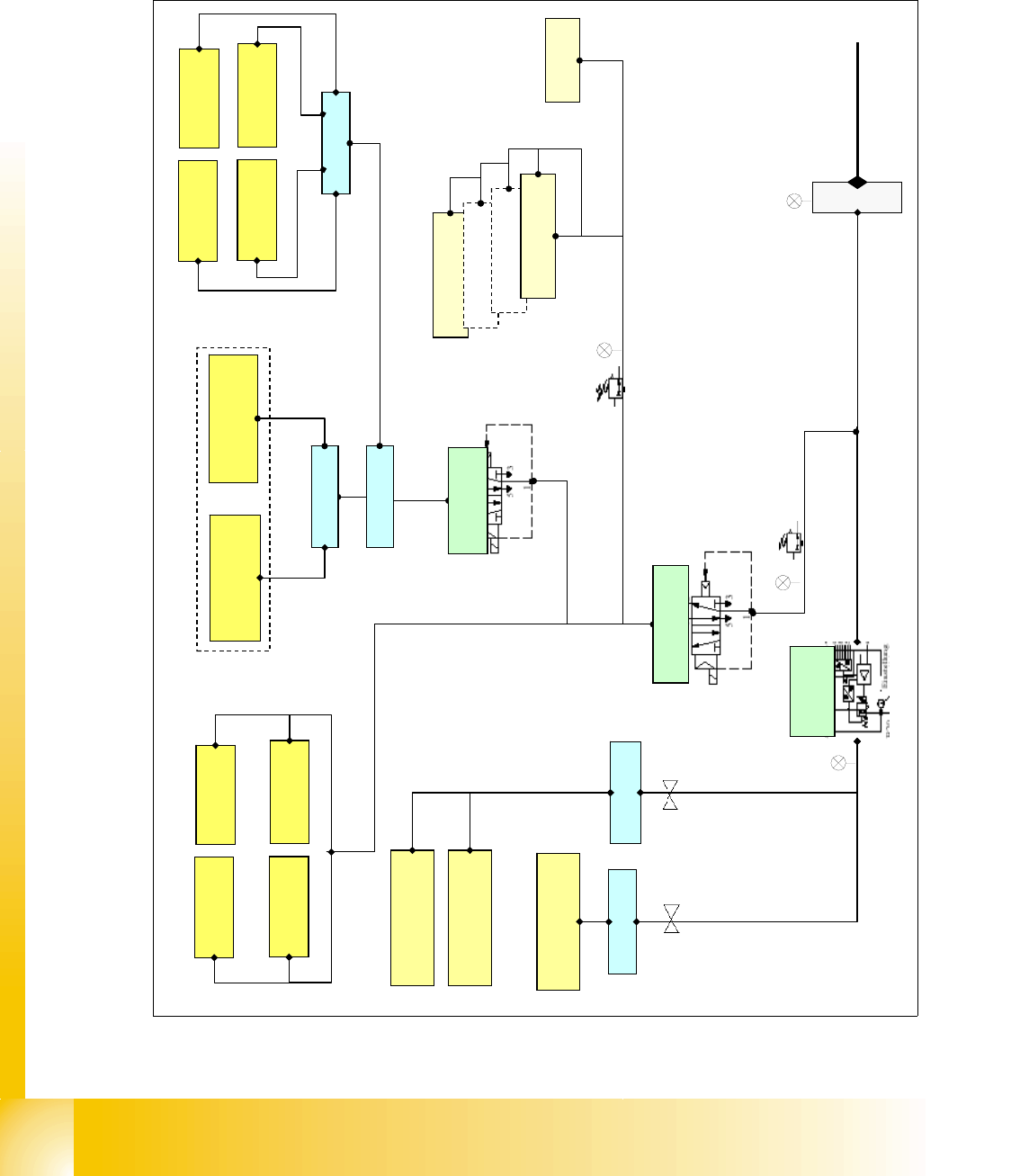
The incoming air supply, specified 5-10 bar passes through the filter and is split into 2 main path.
1st path is into the main regulator and 2nd. path is into the proportional valve.
Fig. 4.3 - 1 pneumatic overview
prop valve
X58
docking unit 3
docking unit 4
docking unit 1
docking unit 2
tape cutter 4
tape cutter 1
tape cutter 2
tape cutter 3
distributor
bulk case
Input pressure
5-10 bar
Collect and place
head
Twin Head 2
Twin Head 1
distributor
distributor
4
.
6
+
0
.
1
b
a
r
5
+
0
.
1
b
a
r
2.5 +-0.5 bar
adjustable
4.6+0.1 bar
not adjustable
width
adjustment
lifting table
distributor
5+
0.1 bar
adj
us
tabl
e
nozzle changer 4
nozzle changer 3
nozzle changer 2
nozzle changer 1
safety valve
X60
distributor
main valve X59
5
+
0
.
1
b
a
r
5
+
0
.
1
b
a
r
2
.
5
+
-
0
.
5
b
a
r
docking unit for co-table 1-4
1 - 35
Student Guide SIPLACE HF/HF3
Edition 09/2005 4 Services to the machine
35
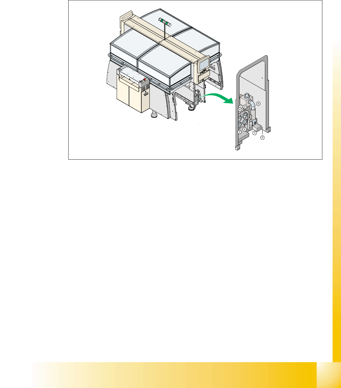
4.3.3 Pneumatic unit
The pneumatic unit is mounted on a compact slide-in module, and located on the right side of the
middle section. A lockable door prevents access to the unit and it contains the whole compressed
air supply and the SMEMA or Siemens interface to the previous and next stations.
Fig. 4.3 - 2 main pneumatic unit
The incoming air (5-10 bar) passes the filter and the manometer ’input pressure’ (no. 1, see next
page) and is then split into 2 main path:
path 1: proportional valve X58 for regulating 5.0 +0.1 bar output (automatically adjusted)
– collect and place head (input at the head 4.6 +0.1 bar)
– TWIN-head segment 1 (input at the head 4.6 +0.1 bar)
– TWIN-head segment 2 (input at the head 4.6 +0.1 bar)
path 2: main valve X59 for regulation 5 +0.1 bar (manually adjusted)
– docking unit (co-table)
– transport (width adjustment and liftng table)
– throttle for manually adjustment of the air pressure used for bulk case and nozzle changer
reduced to 2.5 +-0.5 bar
– safety valve X60 for tape cutter and transport