SG_FSE_SiplaceHF_HF3_00193901-05_eng.pdf - 第149页
1 - 35 S tudent Guide SIPLACE HF/HF3 Edition 09/2005 4 Servic es to the machine 35 4.3.3 Pneumatic unit The pneumatic unit is mounted on a compact slide- in module, and located on the right side of the middle section . A…
1 - 34
Student Guide SIPLACE HF/HF3
4 Services to the machine Edition 09/2005
34
4.3.2 HF Pneumatic System
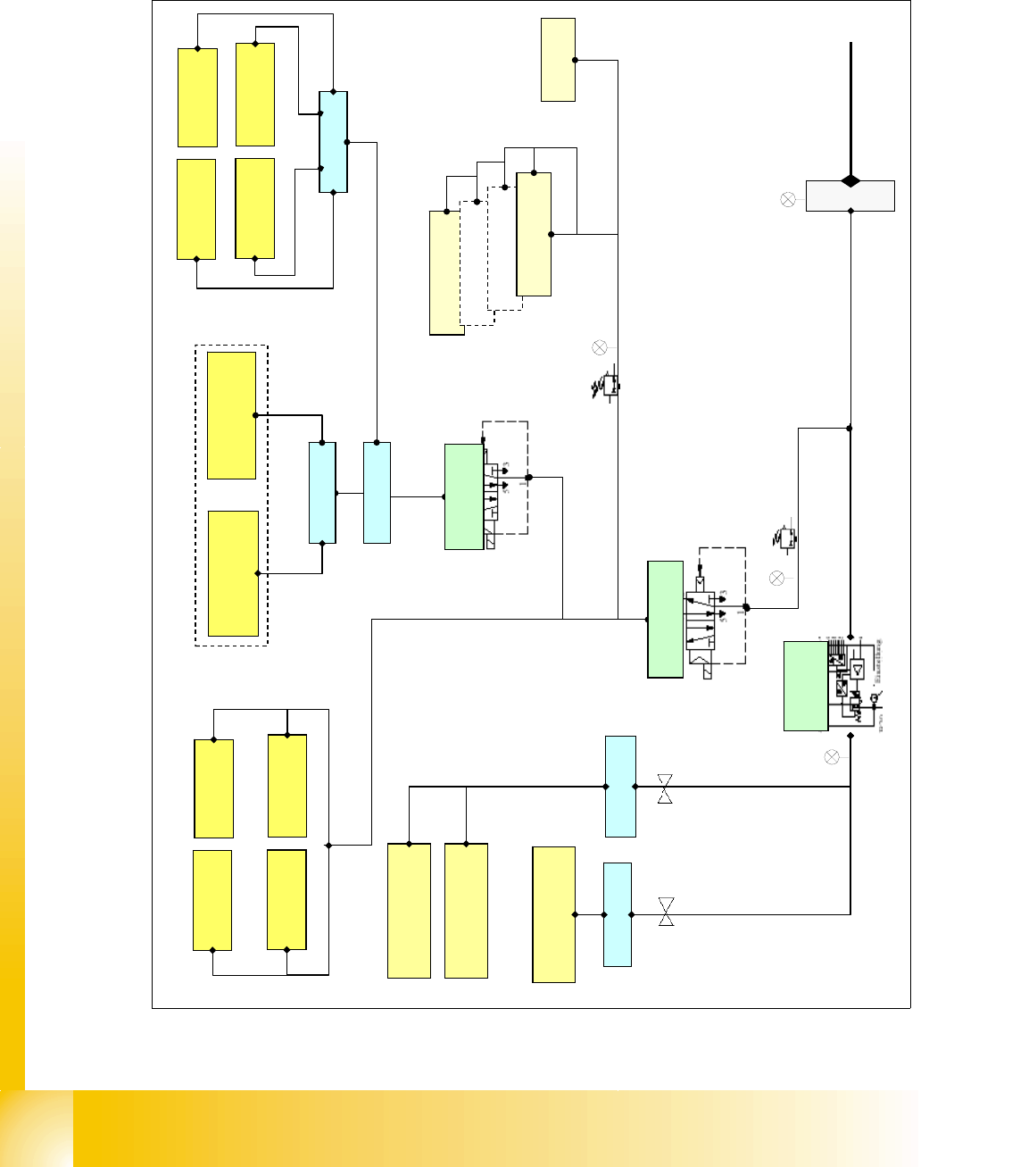
The incoming air supply, specified 5-10 bar passes through the filter and is split into 2 main path.
1st path is into the main regulator and 2nd. path is into the proportional valve.
Fig. 4.3 - 1 pneumatic overview
prop valve
X58
docking unit 3
docking unit 4
docking unit 1
docking unit 2
tape cutter 4
tape cutter 1
tape cutter 2
tape cutter 3
distributor
bulk case
Input pressure
5-10 bar
Collect and place
head
Twin Head 2
Twin Head 1
distributor
distributor
4
.
6
+
0
.
1
b
a
r
5
+
0
.
1
b
a
r
2.5 +-0.5 bar
adjustable
4.6+0.1 bar
not adjustable
width
adjustment
lifting table
distributor
5+
0.1 bar
adj
us
tabl
e
nozzle changer 4
nozzle changer 3
nozzle changer 2
nozzle changer 1
safety valve
X60
distributor
main valve X59
5
+
0
.
1
b
a
r
5
+
0
.
1
b
a
r
2
.
5
+
-
0
.
5
b
a
r
docking unit for co-table 1-4
1 - 35
Student Guide SIPLACE HF/HF3
Edition 09/2005 4 Services to the machine
35
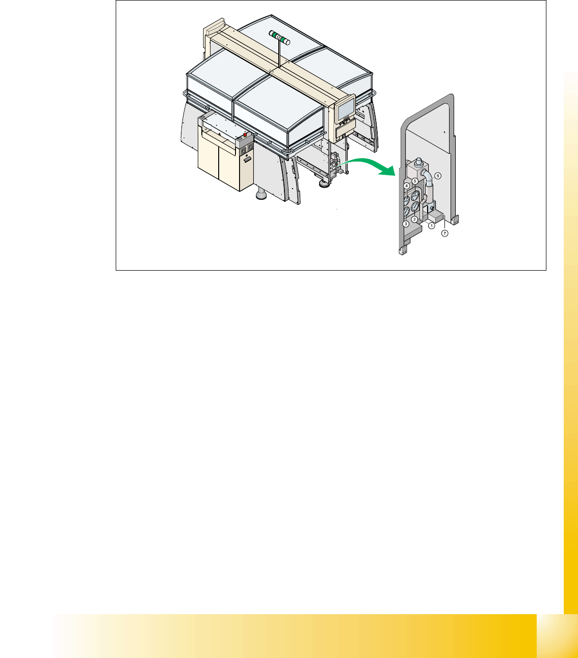
4.3.3 Pneumatic unit
The pneumatic unit is mounted on a compact slide-in module, and located on the right side of the
middle section. A lockable door prevents access to the unit and it contains the whole compressed
air supply and the SMEMA or Siemens interface to the previous and next stations.
Fig. 4.3 - 2 main pneumatic unit
The incoming air (5-10 bar) passes the filter and the manometer ’input pressure’ (no. 1, see next
page) and is then split into 2 main path:
path 1: proportional valve X58 for regulating 5.0 +0.1 bar output (automatically adjusted)
– collect and place head (input at the head 4.6 +0.1 bar)
– TWIN-head segment 1 (input at the head 4.6 +0.1 bar)
– TWIN-head segment 2 (input at the head 4.6 +0.1 bar)
path 2: main valve X59 for regulation 5 +0.1 bar (manually adjusted)
– docking unit (co-table)
– transport (width adjustment and liftng table)
– throttle for manually adjustment of the air pressure used for bulk case and nozzle changer
reduced to 2.5 +-0.5 bar
– safety valve X60 for tape cutter and transport
1 - 36
Student Guide SIPLACE HF/HF3
4 Services to the machine Edition 09/2005
36
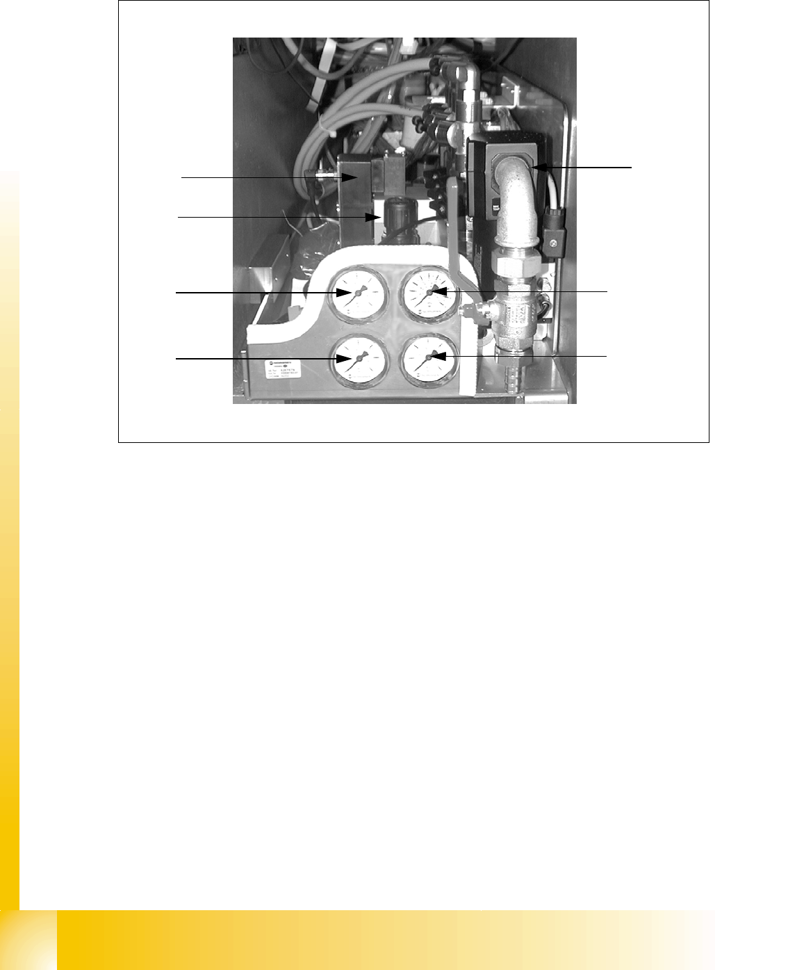
4.3.3.1 Manometer Arrangement
Fig. 4.3 - 3 main pneumatic unit: manometer arrangement
Legend:
1. Manometer for input pressure 5-10 bar
2. Manometer for bulk case and nozzle changer 2.5 +-0.5 bar
3. Manometer for gantries 5.0 +0.1 bar (vacuum for C&P head and Twin head)
4. Mmanometer for machine units 5.0 +0.1 bar (tape cutter, transport, docking unit (co-table)
5. Pressure sensor proportional valve (placement heads)
6. Filter
7. Regulator for machine units (Tape cutter, Transport, Docking unit, COT)
1
4
6
5
2
3
7