SG_FSE_SiplaceHF_HF3_00193901-05_eng.pdf - 第152页
1 - 38 S tudent Guide SIPLACE HF/HF3 4 Services to the machine Edition 09/2005 38 4 Fig. 4.3 - 5 overview pneumatic unit (distribution b lock) e nd: c ut o f val ves gant r ie s s upply doc ki ng uni t s b ulk c ase Fe e…
1 - 37
Student Guide SIPLACE HF/HF3
Edition 09/2005 4 Services to the machine
37
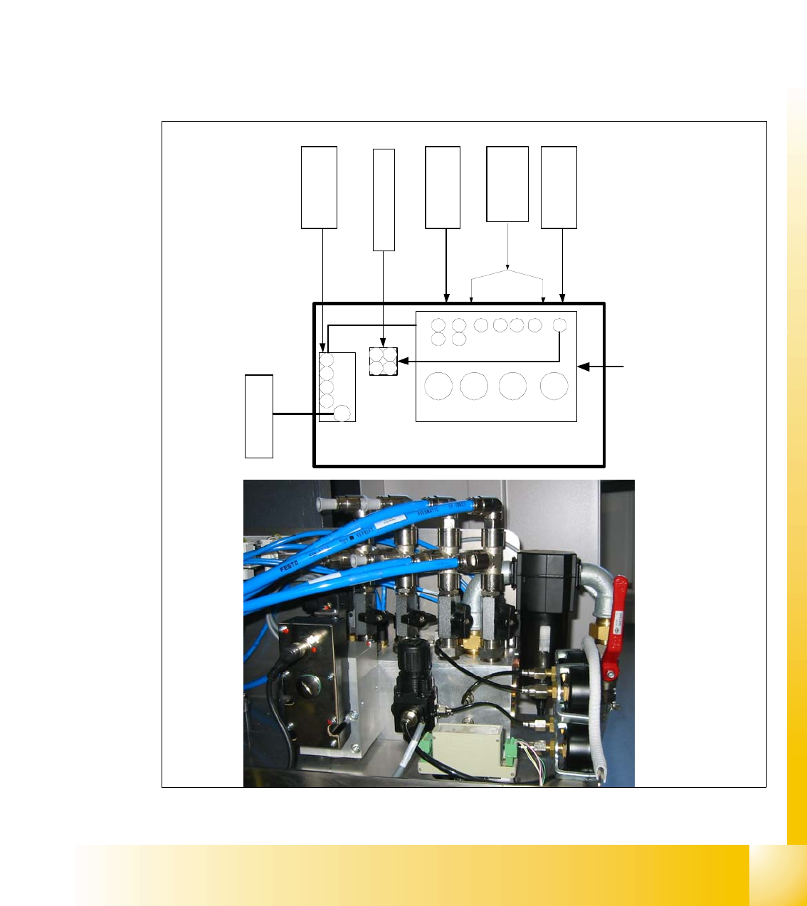
4.3.3.2 Compressed air distribution in Main Pneumatic Unit
The picture below illustrates the compressed air distribution:
– gantry1-2: air supply through 2 hoses (gantry 3/4 not used)
– tape cutter 1-4: air supply through 4 hoses
– docking unit (co-table) 1-4: air supply through 4 hoses
– bulk case 1-4: air supply through 4 hoses
– nozzle changer 1-2: air supply through 2 hoses
– transport: air supply with 1 hose
Fig. 4.3 - 4 pneumatic distribution block in main pneumatic unit HF
3
4
2
1
gantry 1 - 4
4
3
2
1
bulkcase
1-4
2,5 bar
adjustable
nozzle
changer
1 2
34
nozzle changer
2,5 bar
adjustable
docking unit
(co-table)
5 bar
adjustable
conveyor
5 bar
adjustable
5 bar
adjustable
1 2 3 4
compressed air distribution block
tape cutter
1 - 4
4 3
21
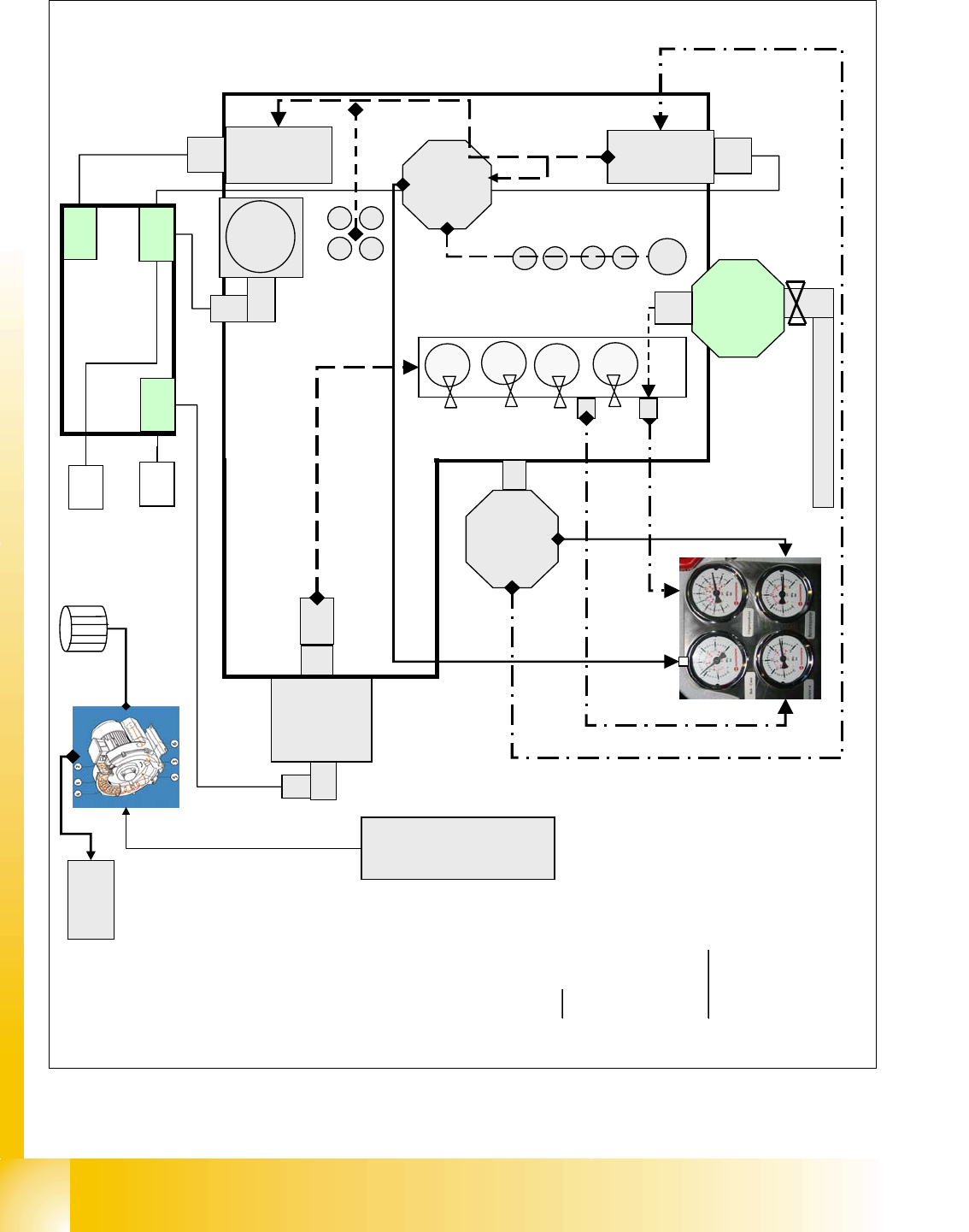
1 - 38
Student Guide SIPLACE HF/HF3
4 Services to the machine Edition 09/2005
38
4
Fig. 4.3 - 5 overview pneumatic unit (distribution block)
e
nd:
c
ut of valves gantries
s
upply docking units
b
ulk case Feeder&nozzle changer
s
upply tape cutter/Transport
s
tart and control Y-drive cooling
ometers:
put pressure
u
pply of bulk case Feeder/nozzle
n
ger 2.5 bar
e
ct
r
. regulated supply of gantries
u
pply ‘machine’ 5 bar include
k
ing units tape cutters/PCB
v
ey.
main air input 5-10 bar
X60
Y-axis cooling motor
control device
Y-axis cooling motor
pressure
sensor
S
h
u
t
-
o
f
f
v
a
l
v
e
prop.
valve
5 bar
safety valve
filter
regulator
5 bar
1
3
2
4
regulator
2.5 bar
main valve
power and motor control signal
power and control signal
power and control signal
Y axis
motor
power and
control signal
5 bar
5
b
a
r
5 -10 bar
4.8 bar
(4)
(3)
(2)
(1)
connector
board
4.8 +0.1 bar
compressed air
distribution block
5 bar
K2
K1
X58
X59
2
.
5
b
a
r
(5)
1 - 39
Student Guide SIPLACE HF/HF3
Edition 09/2005 4 Services to the machine
39
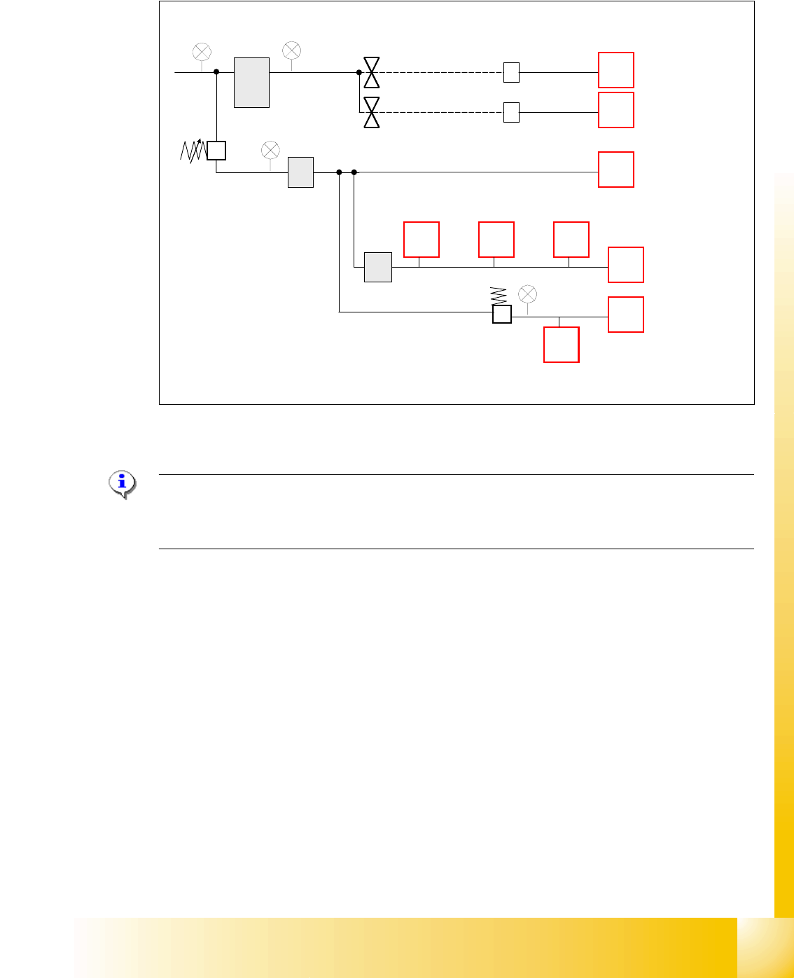
4.3.3.3 Switch on Sequency Pneumatic Units
Fig. 4.3 - 6 switch on sequency pneumatic
Please Note: Prop. valve X58, controlled by relay K2, is immediately powered with machine ON.
After the reference run is performed, the valve X58 can be switched off by soft-
ware (as a standard 2 minutes).
The time to deactivate the prop. valve can be changed in station software
4
– settings
– configure compressed air deactivation
– switch off after 1-60 minutes
5-10 bar
4,6+-0.1bar
2,5 ± 0,5 bar
proportional
valve (controlled
by K2)
main valve, ON with
power on (controlled by K1)
safety valve, ON/OFF
8controlled by SSK)
placement head 1
docking station
(co-table 1-4)
placement head 2
tape cutter 1-4
PCB transport,
lifting table
PCB transport,
width adjustment
PCB stopper’ long
board option’
nozzle changer
C&P head
bulk case option
X58
X59
X60