SG_FSE_SiplaceHF_HF3_00193901-05_eng.pdf - 第159页
1 - 45 S tudent Guide SIPLACE HF/HF3 Edition 09/2005 4 Servic es to the machine 45 4.3.5 Pneumatic Supply Docking Unit (Compnent-t able 1-4) Fig. 4.3 - 15 pneumatic supply docking unit (co-table) 4.3.6 Bulk Case System a…
1 - 44
Student Guide SIPLACE HF/HF3
4 Services to the machine Edition 09/2005
44
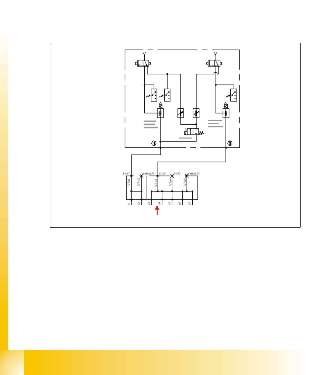
4.3.3.8 Pneumatic loop Cooling X - Linear motor for Placement area 1
For cooling the X-motors the exhausting air of the vacuum generator of C&P head and Twin head
is used. The cooling system for the Twin head in placement area 2 is quite similar. to the y-axis
cooling system. The major difference is the air distributor, which spread the air from both sides to
the x-axis on Twin head.
Fig. 4.3 - 13 cooling system X-axis motor
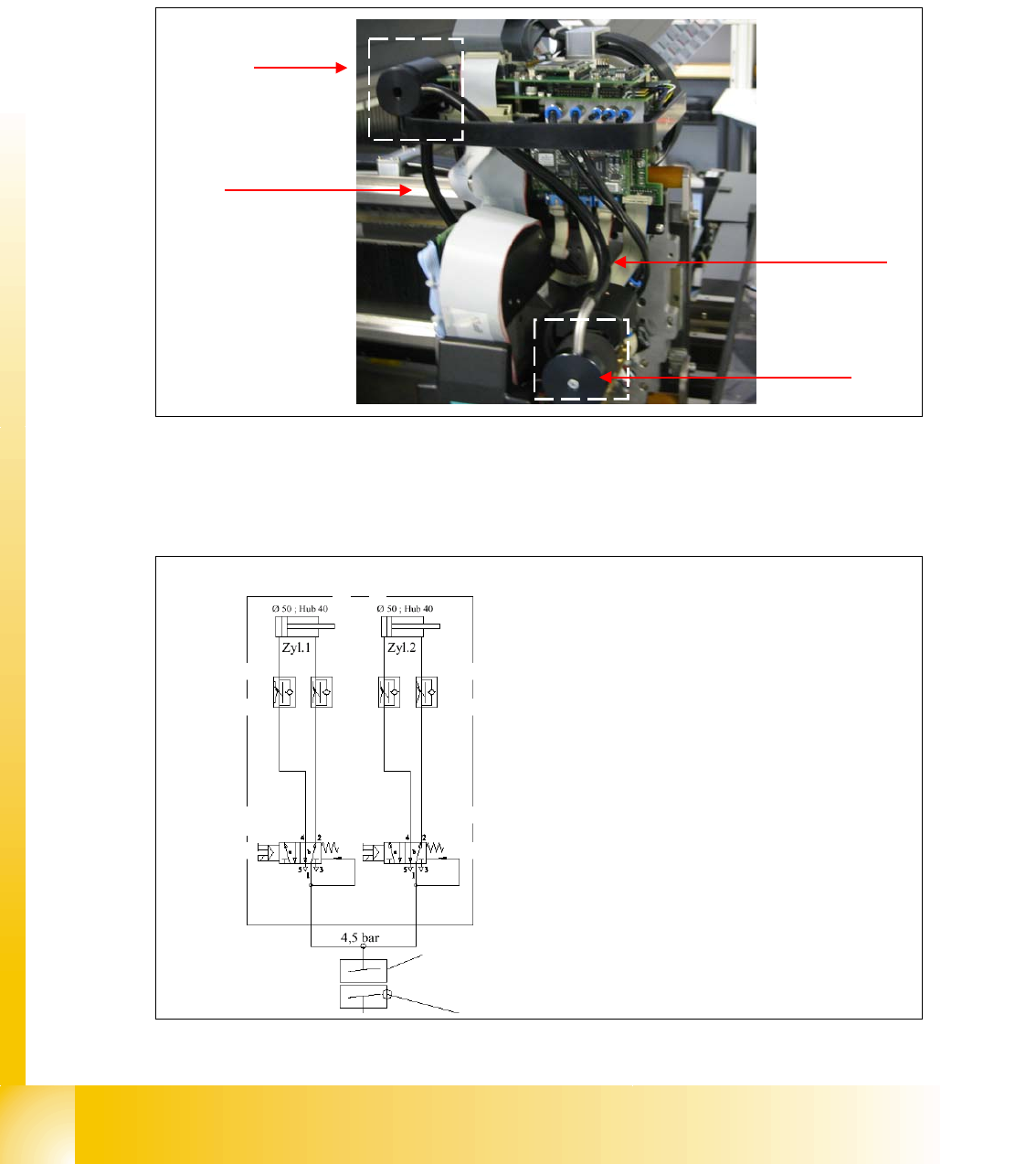
4.3.4 Pneumatic Supply Tape Cutter
Fig. 4.3 - 14 pneumatic supply tape cutter
air distributor
silencer
air pipe for cooling
the x-axis
pipe for air supply
to distributor
3
2
1
4
Legend:
1: drive cylinder for cutting edge movement
40 mm
2: adjustable throttle according to the cylinder
3: 5/2 valve
4: air supply 5 bar switched with SSK (when
SSK is energized)
valve 1 valve 2
cylinder 1 cylinder 2
1 - 45
Student Guide SIPLACE HF/HF3
Edition 09/2005 4 Services to the machine
45
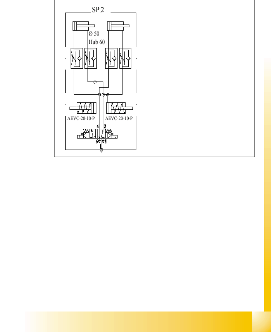
4.3.5 Pneumatic Supply Docking Unit (Compnent-table 1-4)
Fig. 4.3 - 15 pneumatic supply docking unit (co-table)
4.3.6 Bulk Case System and Nozzle Changer
A further adjustable regulator is used to reduce the 5.0 bar to 2.5 +0.5 bar. This air supply is
presently used for the bulk case feeder system and for the npzzle changer
.
3
2
1
4
Legend:
1: drive cylinder for locking device, table
movement 43 mm
2: adjustable throttle on the cylinder
3: cylinder for table release (push out) 10mm
movement
4: air supply 5+-0.1 bar
1 - 46
Student Guide SIPLACE HF/HF3
4 Services to the machine Edition 09/2005
46
4.3.7 Pneumatic Supply Collect and Place Haed
The 4.8 bar air supply is used for principle things on the C&P head:
– vacuum
–air kiss
– cooling the X-axis motor.
The major difference here on the DLM 2 head compared with the former DLM 1 head is the cooling
pipe for the X-axis drive
Fig. 4.3 - 16 vacuum distribution on revolving head
Legend:
1. a: Valve for vacuum - air kiss placement (valve plunger) b: Reject position (not used on HF)
2. Air kiss sensor
3. Vacuum sensor for pick-up and placement
4. Vacuum sensor for 11 segments (on a 12 nozzle head) or 5 segments (on a 6 nozzle head) in
holding circuit
5. Venturi vacuum generator
6. Solenoid valve air kiss
air distribution block
Pick up and
placement
circuit
holding circuit
air kiss
air kiss
4.5 bar +0.1 input from gantry
distributor
3
2
1a
4
5
6
1b