SG_FSE_SiplaceHF_HF3_00193901-05_eng.pdf - 第168页
1 - 2 S tudent Guide SIPLACE HF/HF3 5 Gantry Edition 09/2005 2 Fig. 5.1 - 2 Main parts at the "Gantries" e.g. HF Legend Instead of the normal PCB camera (sensor type 5.sst). Y ou can u se the option mu lticolor…
1 - 1
Student Guide SIPLACE HF/HF3
Edition 09/2005 5 Gantry
1
5Gantry
5.1 Overview Gantry
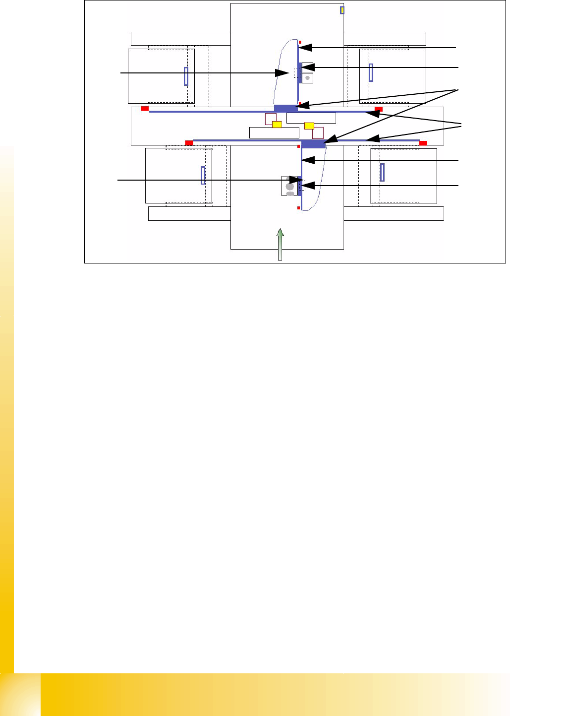
The 2 gantries of the HF machine or the three gantries of the HF3 machine consist of one X- and
one Y - axis. Both axes are driven by a linear motor which is equipped with an integrated temper-
ature sensor. The Y-axis moves from the right to the left side in positive counting direction if you
look in transportation direction, the X-axis moves from the the input conveyor to the output con-
veyer in positive counting direction. The placement heads are mounted on the head plates of the
respective X axis.
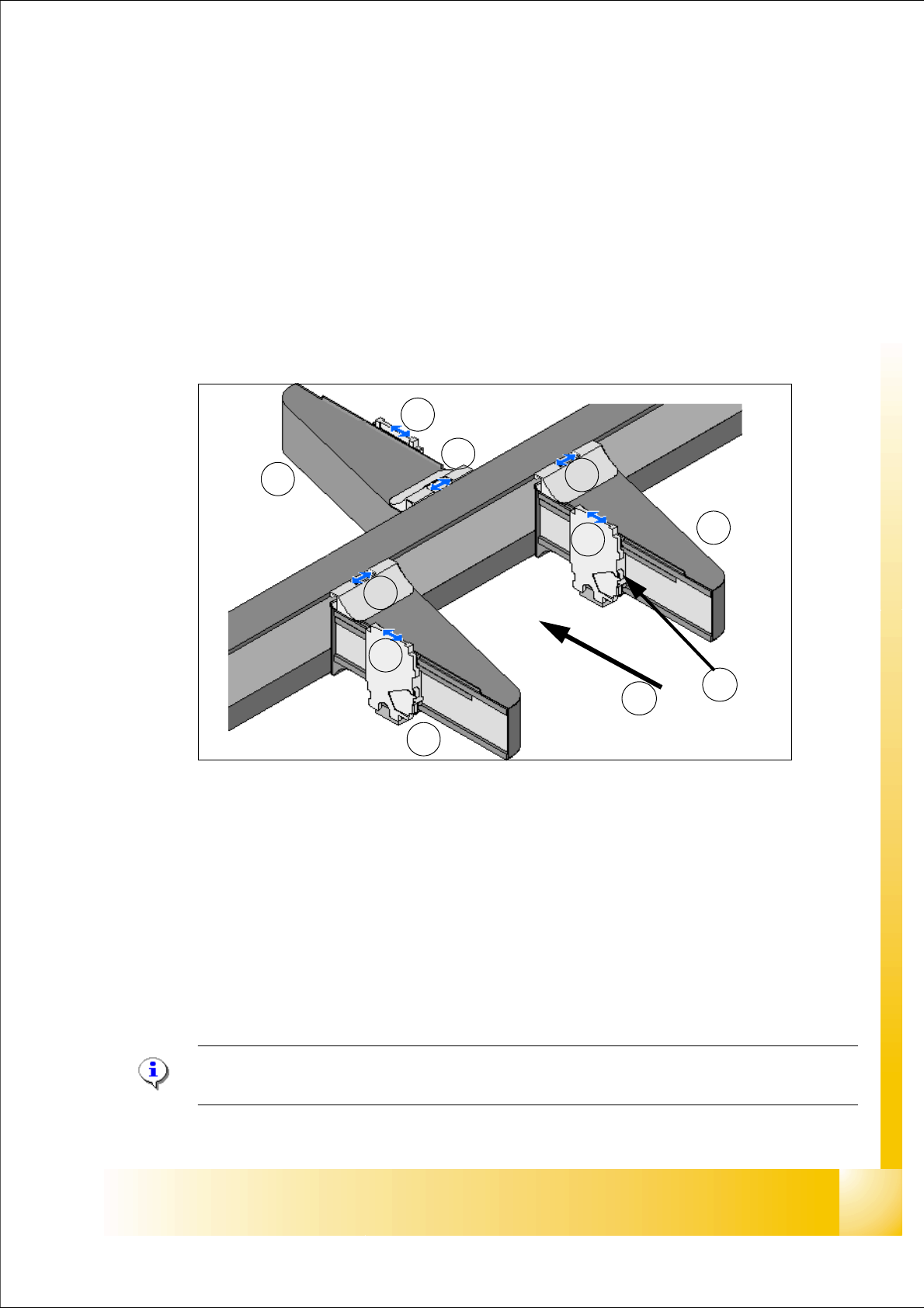
Fig. 5.1 - 1 Position of the gantries HF3
Legend:
Please Note: On the HF machine are only two gantries. The name of this Gantries with Sta-
tionsoftware 505.xx are Gantry 1 and Gantry 3.
G1Gantry 1 in PA1 G3Gantry 3 in PA2
X1X-Axis, Gantry 1 X3X-Axis, Gantry 3
Y1Y-Axis, Gantry 1 Y3Y-Axis, Gantry 3
G4Gantry 4 in PA 1
X4X-Axis, Gantry 4 (T)Transportation direction
Y4Y-Axis, Gantry 4 (TS)Temperature sensor on each head mounting plate
G4
G1
G3
Y4
Y3
Y1
X4
X3
X1
T
TS
1 - 2
Student Guide SIPLACE HF/HF3
5 Gantry Edition 09/2005
2
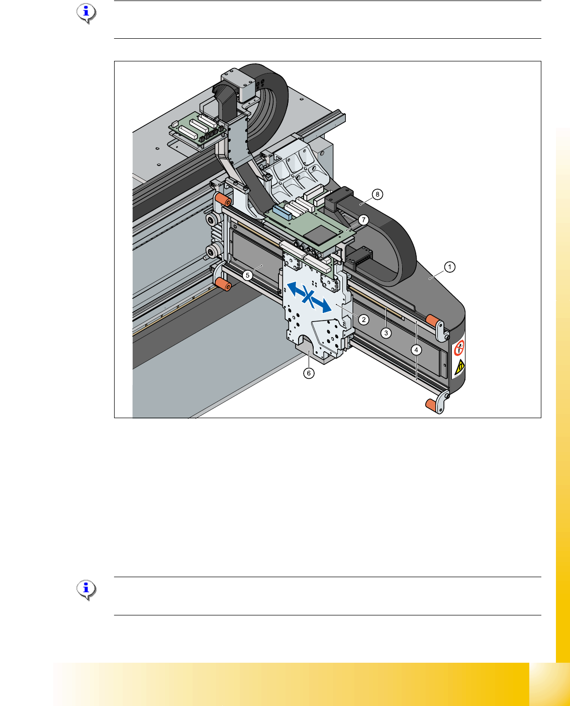
Fig. 5.1 - 2 Main parts at the "Gantries" e.g. HF
Legend
Instead of the normal PCB camera (sensor type 5.sst). You can use the option multicolor camera
(sensor type 18.sst).
The advantage of the multicolor camera is the fiducial recognition on ceramic substrate on ac-
count of different illumination colors.
(1) Secondary part X-axis (Magnet) (2) Primary part X-axis (Linear motor)
(3) Primary part Y-axis (Linear motor) (4) Secondary part Y-Axis (Magnet)
(5) Secondary part X-axis (Magnet) (6) Primary part X-axis (Linear motor)
(7) PCB camera under the X-axis (8) PCB camera mounted under the gantry
1
2
3
4
5
6
7
8
1 - 3
Student Guide SIPLACE HF/HF3
Edition 09/2005 5 Gantry
3
5.1.1 Mechanical structur of the X- and Y- axes
Please Note:
X- and Y- Axes have the same basic mechanical parts.
Fig. 5.1 - 3 Mechanical structure "Gantry"
Legend
Please Note: The temperature sensor compensates according the temperature of the head
mounting plate the offset between PCB camera and nozzle to ensure the highest accuracy.
(1) X-axis (carbon fiber composite material) (2) Head mounting plate with integreted temperatur sensor
(3) Incremental scale X-Axis (4) Linear guidance (above/below the magnet)
(5) Secondary part X-axis (Magnet) (6) PCB-camera below the X-axis
(7) Boards (Head interface with Vision board
below -vertical- is the Adapter board)
(8) X- trailling cable