SG_FSE_SiplaceHF_HF3_00193901-05_eng.pdf - 第174页
1 - 8 S tudent Guide SIPLACE HF/HF3 5 Gantry Edition 09/2005 8 Notes:

1 - 9
Student Guide SIPLACE HF/HF3
Edition 09/2005 5 Gantry
9
5.3 Adjustments
5.3.1 Travel range and velocity monitoring X- and Y- Axes on the HF
The travel range of the X- and Y-axes will be determined automatically with Sitest program. That
means, during calibration of travel range the axis run as far as possible into its minimum and/or
maximum position. The axis position is taken when the limit-BERO´s switch. Corresponding the
description (see below) a safety space infront of the hardware limit switch is calculated for SW-
travel limit.
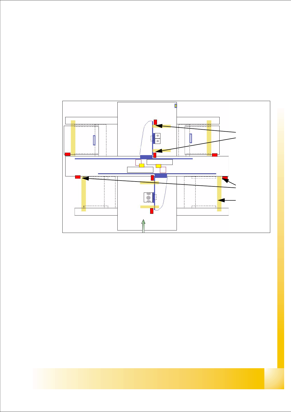
Fig. 5.3 - 1 Travel range X- and Y-axes
Legend
a The end of the travel range of the X-axis be + or - 0,5 mm before the hardware limit switch
(software limit switch).
For velocity check, a range of
45 mm before the hardware limit switch was determined. This
way is sufficient, if the X- axis move with to high velocity into this field. It will be stop by the anti
crash board immediately.
s The end of the travel range of the Y-axis be + or - 1,5 mm before the hardware limit switch
(software limit switch).
For velocity check, a range of
65 mm before the hardware limit switch was determined. This
way is sufficient, if the Y- axis move with to high velocity into this field. It will be stop by the anti
crash board immediately.
(1) Travel range (min./max.pos.) X-axis (2) Travel range (min./max.pos.)Y-axis
(3) those areas show the range with reduced speed near the bumpers
1
2
3