SG_FSE_SiplaceHF_HF3_00193901-05_eng.pdf - 第177页
1 - 1 1 S tudent Guide SIPLACE HF/HF3 Edition 09/2005 5 Gantry 11 5.3.2.1 Adjustment s BERO‘s On each axis are two BERO ‘s insta lled, which need a dist ance about 0,4 mm to the metal a ctuator . The metal actu ator are …
1 - 10
Student Guide SIPLACE HF/HF3
5 Gantry Edition 09/2005
10
5.3.2 Travel range and velocity monitoring X- and Y- Axes on the HF 3
The travel range of the X- and Y-axes will be determined automatically with Sitest program. That
means, during calibration of travel range the gantry 3 went as far as possible into its minimum and
maximum position. Corresponding the description (see travel range HF) a safety space in front of
the hardware limit switch is calculated. At HF 3 machine we have two gantries in the placement
area 1 so the Y-axis of the gantry 1 went to the minimum position and the Y-axis of gantry 4 went
to the maximum position. After that we calculate the minimum position for gantry 4 according min.
pos. of gantry 1. The maximum position for gantry 1 we calculate on the result of maximum pos.
of gantry 4.(see below)
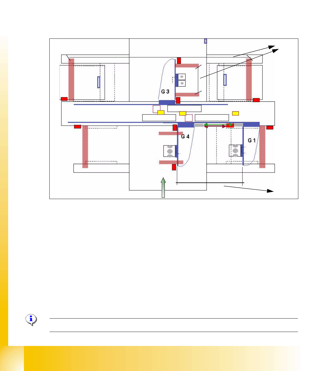
Fig. 5.3 - 2 Travel range X- and Y-axes HF3 machine
(1) The calculation of the travel range for the X-axes on gantries 1 / 3 / 4 and Y-axes from the
gantry 3 is the same as the HF machine.
(2) The travel range for the y-axes on the gantries 1 and 4 are calculated partly. That means, the
Y-axis of Gantry 1 moves into the minimum position and the Y-axis of gantry 4 moves into the
maximum position. The calculation is:
Maximum position gantry 1 = Maximum position gantry 4 - 480mm (gantry width) - 20mm
safety space.
Minimum position gantry 4 = Minimum position gantry 1 + 480mm (gantry width) + 20mm
safety space.
(3) Safety space approx. 20mm
Please Note: For adjust the Anti Crash board see 5.3.4.
1
2
3
1 - 11
Student Guide SIPLACE HF/HF3
Edition 09/2005 5 Gantry
11
5.3.2.1 Adjustments BERO‘s
On each axis are two BERO‘s installed, which need a distance about 0,4 mm to the metal actuator.
The metal actuator are installed on the left and right side from the incremental scale. Adjust cor-
rectly the distance with a
feeler gauge of 0,4 mm. After this adjustment calibrate the travel range
for the respective axis with the Sitest program.
5.3.2.2 Description of the BERO‘s on the Y-Axis
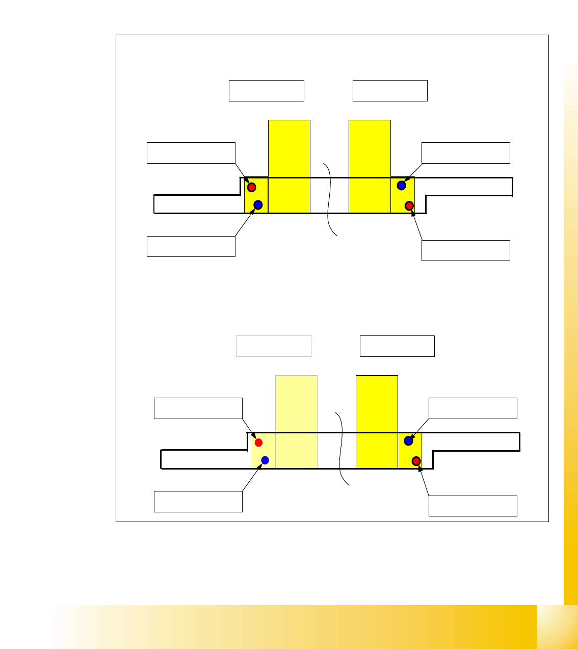
Fig. 5.3 - 3 Positions of the BERO‘s depend on the gantries
– Theoretical position of the BERO‘s if gantry 2 available.
Triggering plate Y - Axes HF 3 for
Placement area 1
Gantry 4 Gantry 1
Reference - BERO
Gantry 4
BERO - Limit switch
Gantry 4
Reference - BERO
Gantry 1
BERO - Limit switch
Gantry 1
Triggering plate Y - Axes HF 3 for
Placement area 2
Gantry 2 Gantry 3
Reference - BERO
Gantry 2
BERO - Limit switch
Gantry 2
Reference - BERO
Gantry 3
BERO - Limit switch
Gantry 3
1 - 12
Student Guide SIPLACE HF/HF3
5 Gantry Edition 09/2005
12
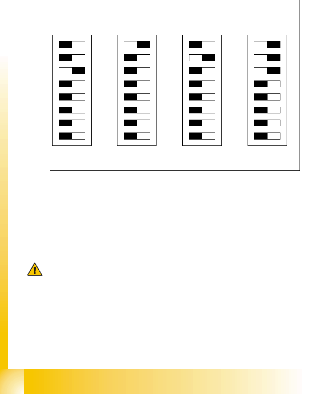
5.3.3 Check the DIP Switches
5.3.3.1 DIP Switches on the head interface
Legend for DIP Switches
Attention:
With Head Modularity pay attention: That terminating CAN resistor is set correctly. That means, at
the C&P heads switch CAN-Terminator ON and at the TWIN-head switch it OFF.
(1) P0 - Gantry address switch 1 (2) P1 - Gantry address switch 2
(3) CAN R - CAN terminator
(At TWIN-option always OFF)
(4) Boot - CAN Processor 16 Bit not mounted
(5) Reset - CAN Processor 16 Bit not mounted (6) C0 - CAN Address switch
(7) C1 - CAN Address switch (8) WPE - Write protect enable at the moment
OFF
DIP Switch
ON
78123456
ON
78123456
ON
78123456
ON
78123456
Gantry 1
Gantry 2
not used
Gantry 3 Gantry 4
C&P Head
C&P Head
Twin Head