SG_FSE_SiplaceHF_HF3_00193901-05_eng.pdf - 第184页
1 - 18 S tudent Guide SIPLACE HF/HF3 5 Gantry Edition 09/2005 18 T est procedure 5 ➠ Connect the track signal tester on the incre mental enco der . ➠ Switch "ON" the main switch ➠ Connect the oszilloscope on th…
1 - 17
Student Guide SIPLACE HF/HF3
Edition 09/2005 5 Gantry
17
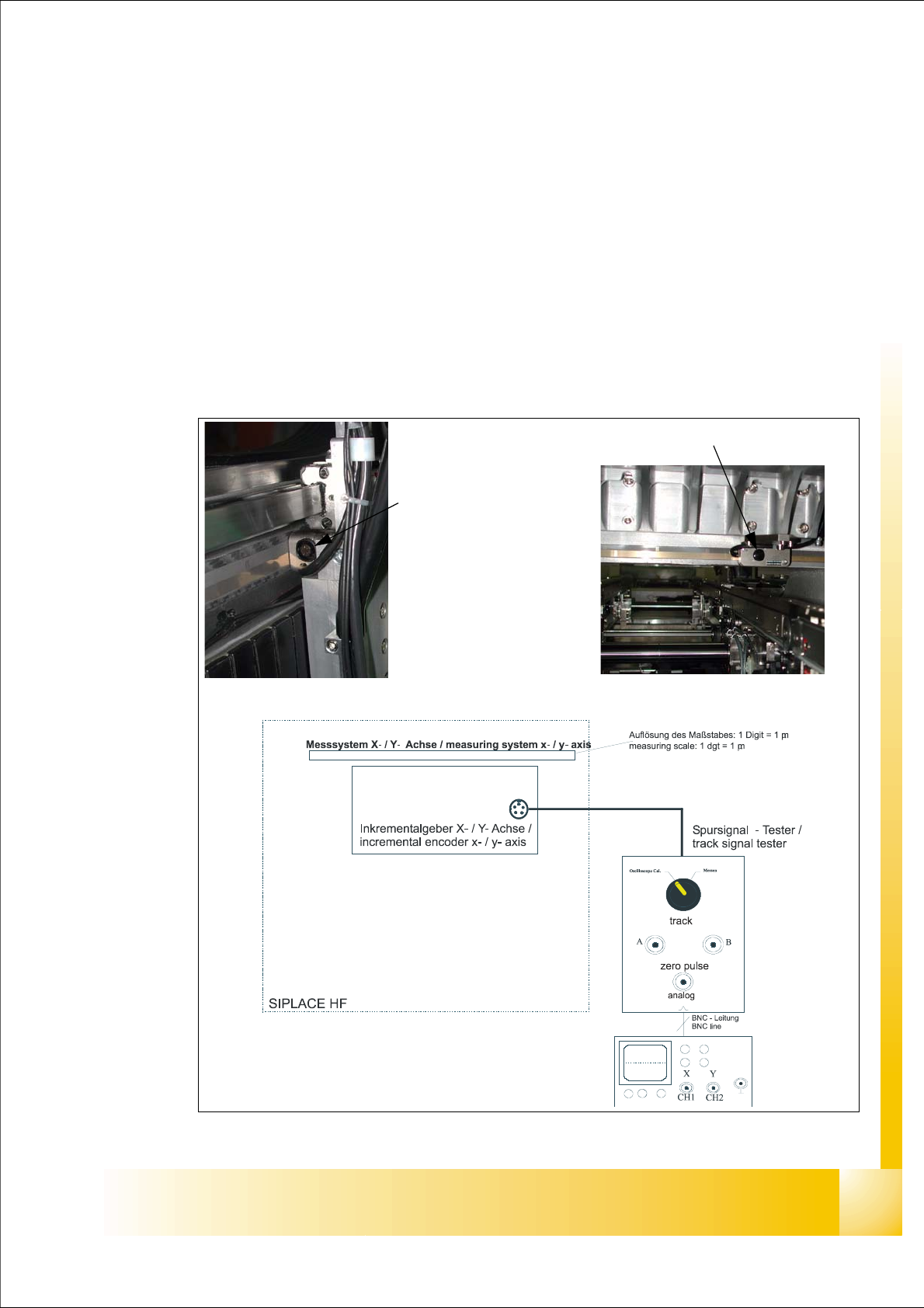
5.4 Track signals and Zero pulse
5.4.1 Check the zero pulse signal
The zero pulse on the incremental scale must be recognize from the incremental encoder secure
and perfectly. To check the zero pulse you can check the analog or digital zero pulse.
If the zero pulse is not recognize correctly, the axis will reference to a spurious peak. Placement
offsets will be the result.
On the incremental measurement you can‘t make any electrical adjustments.
5.4.1.1 Measurement the analog zero pulse signal
Fig. 5.4 - 1 Test setup to check the analog zero pulse and track signals
Incremental encoder
X - Axis
Incremental encoder X - Axis
1 - 18
Student Guide SIPLACE HF/HF3
5 Gantry Edition 09/2005
18
Test procedure 5
➠ Connect the track signal tester on the incremental encoder.
➠ Switch "ON" the main switch
➠ Connect the oszilloscope on the track signal tester.
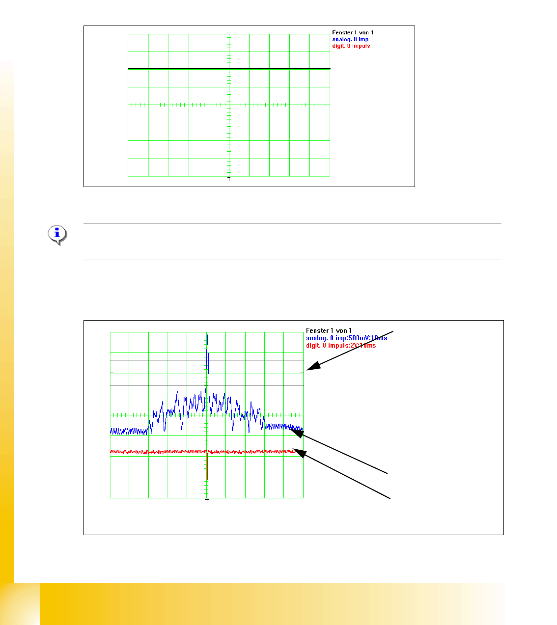
➠ Set the switch to "Oszilloscope calibrate" on the track signal tester.
➠ Positioning the signal to the middle from the upper half of the display. (see picture below)
Fig. 5.4 - 2 Initinal start point to measure the zero pulse.
Please Note:
Check the first zero pulse which you need for the reference run on the incremental scale.
➠ Move by hand the gantry over the first zero pulse.
➠ It should appear the following picture on the oscilloscope.
Fig. 5.4 - 3 Adjustment of the incremental encoder correct
Initial start position
1. In the Tolerance
space of - 0,3 V you
don‘t have an inter-
ference pulse.
2. The analog zero
pulse have to over
the tolerance space
more then 0,3V
analog zero pulse
digital zero pulse
1
2
1 - 19
Student Guide SIPLACE HF/HF3
Edition 09/2005 5 Gantry
19
Fig. 5.4 - 4 Incremental encoder wrong adjusted or poluted zero pulse
Legend
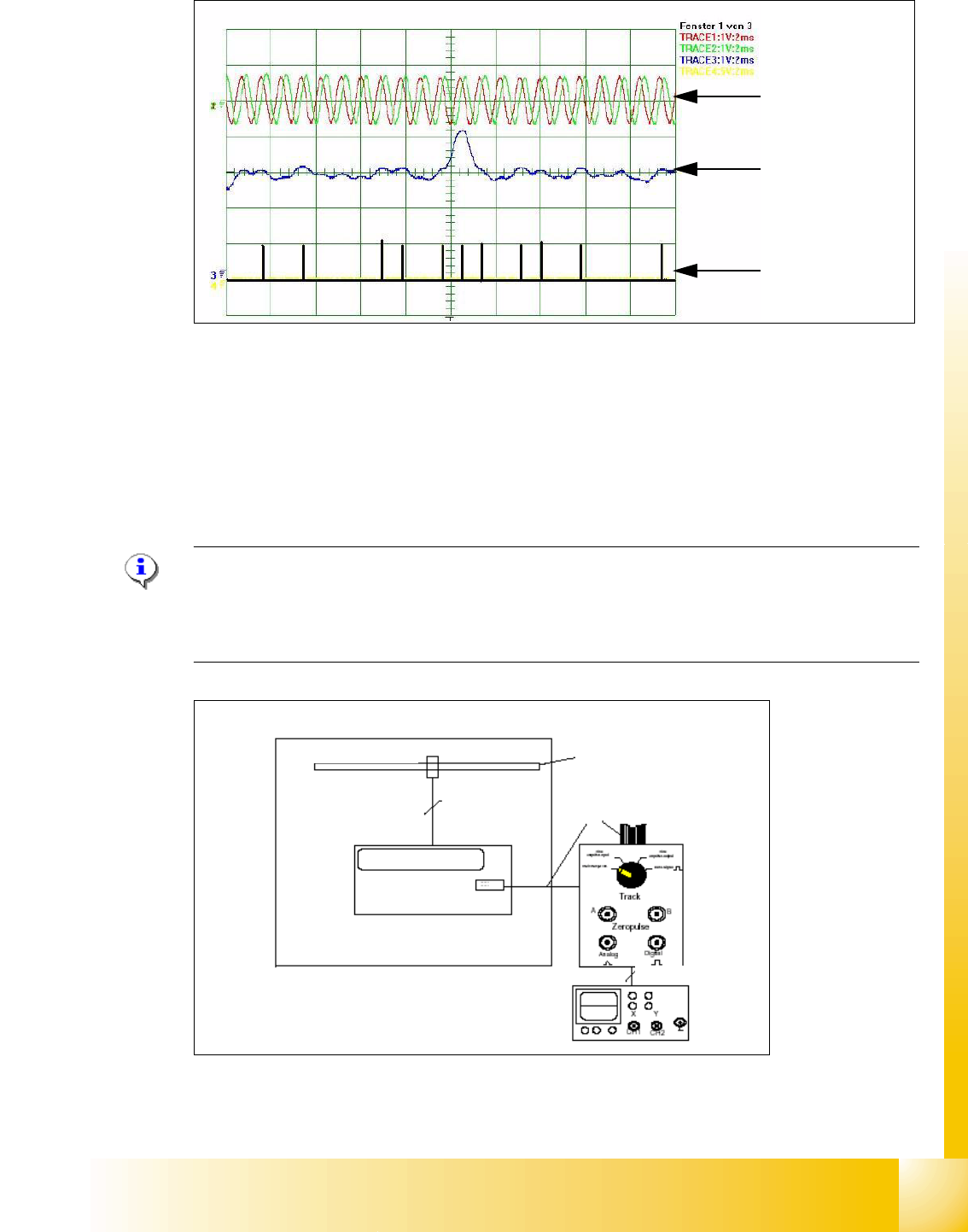
5.4.1.2 Measurement the digital zero pulse signal
Please Note: Also for checking the zero pulse you can use the BNC connector from the axis test
box (inverse signal).
On the connectors X10 and X24 on gantry -and headinterface can you check the digital Signals.
(Y-Axis, more time to dismounting the covers)
Fig. 5.4 - 5 Test setup to check the digital zero pulse and track signals
(1) analog track signal A and B (2) analog zero pulse
(3) digital zero pulses
1
2
3
Test setup for digital zero pulse and track signals
Measurment system X/Y Axis
Track A/B/N
Resolution incremental scale
1 Digit= 1µm
Track signal
tester
BNC-cable
Siplace HF
Board
Test connector
Ribbon cable