SG_FSE_SiplaceHF_HF3_00193901-05_eng.pdf - 第197页
S tudent Guide SIPLACE HF/HF3 Edition 09/2005 Contents 1 Chapter T able of Content s 6 Collect &Place-Head / DLM2 . . . . . . . . . . . . . . . . . . . . . . . . . . . . . . . . . . . . . . . . . . 1 6.1 Overview . .…
1 - 30
Student Guide SIPLACE HF/HF3
5 Gantry Edition 09/2005
30
Please Note:
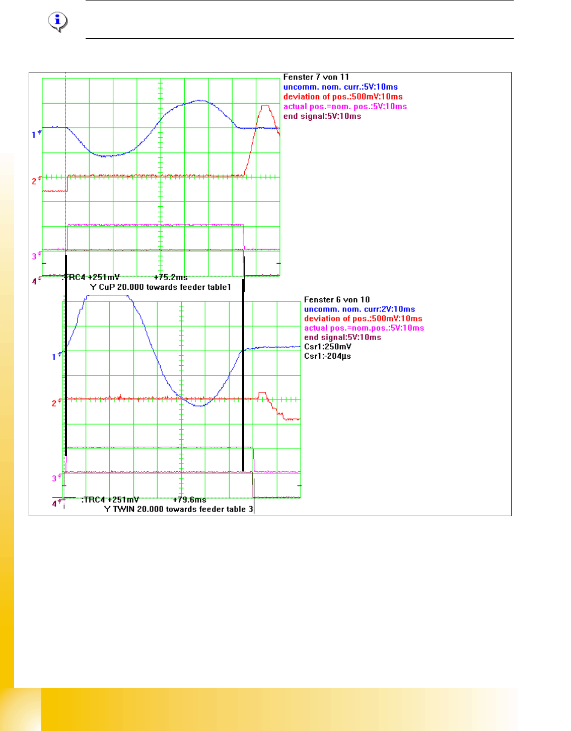
The allowed deviation of position at the C&P head is 10µm and at the twin head 5µm.
Fig. 5.5 - 7 Dynamic Signals at 20000 digit distance of Y-Axis C&P head on top and Twin head at bottom
Legend
3
2
1
(1) Start of the axis (2) Twin head reach the nominal position a little later,
Overshot control don‘t happen.
(3) actual pos. is nominal position signal and end signal at the same time following overshots smaller than
the allowed dev. of pos.

Student Guide SIPLACE HF/HF3
Edition 09/2005 Contents
1
Chapter
Table of Contents
6 Collect &Place-Head / DLM2 . . . . . . . . . . . . . . . . . . . . . . . . . . . . . . . . . . . . . . . . . . 1
6.1 Overview. . . . . . . . . . . . . . . . . . . . . . . . . . . . . . . . . . . . . . . . . . . . . . . . . . . . . . . . . . . . . . . . . . . . . . . 1
6.1.1 Technical Data 6/12 DLM2. . . . . . . . . . . . . . . . . . . . . . . . . . . . . . . . . . . . . . . . . . . . . 2
6.1.1.1 Technical Data: 6 Segment / 12 Segment C&P heads. . . . . . . . . . . . . . . . . . . . . 3
6.1.1.2 Camera modularity at the 6segment C&P head for example. . . . . . . . . . . . . . . . 3
6.1.2 Steps when picking up and placing components. . . . . . . . . . . . . . . . . . . . . . . . . . . . . 4
6.1.3 Position and function of the individual star stations. . . . . . . . . . . . . . . . . . . . . . . . . . . 4
6.1.4 Overview parts on the 12 Segment C&P head . . . . . . . . . . . . . . . . . . . . . . . . . . . . . . 6
6.1.5 Pressure air supply DLM 2 C&P head. . . . . . . . . . . . . . . . . . . . . . . . . . . . . . . . . . . . . 9
6.1.5.1 Vacuum generator DLM 2 . . . . . . . . . . . . . . . . . . . . . . . . . . . . . . . . . . . . . . . . . . 9
6.1.6 Overview air kiss supply . . . . . . . . . . . . . . . . . . . . . . . . . . . . . . . . . . . . . . . . . . . . . . 10
6.1.7 Overview vacuum supply. . . . . . . . . . . . . . . . . . . . . . . . . . . . . . . . . . . . . . . . . . . . . . 11
6.2 Reference Run . . . . . . . . . . . . . . . . . . . . . . . . . . . . . . . . . . . . . . . . . . . . . . . . . . . . . . . . . . . . . . . . . 13
6.2.1 Reference run C&P head . . . . . . . . . . . . . . . . . . . . . . . . . . . . . . . . . . . . . . . . . . . . . 14
6.2.2 Initialize Valve Drive at Pick-up / Placement Position / Reject Position . . . . . . . . . . 15
6.2.3 Initialize Valve Drive at Reject Position which is not use on HF machine. . . . . . . . . 16
6.2.4 Initialize Valve Drive at DP-station . . . . . . . . . . . . . . . . . . . . . . . . . . . . . . . . . . . . . . 17
6.2.5 Preparing Z-axis Reference Run. . . . . . . . . . . . . . . . . . . . . . . . . . . . . . . . . . . . . . . . 18
6.2.6 Reference Run at Star-Axis. . . . . . . . . . . . . . . . . . . . . . . . . . . . . . . . . . . . . . . . . . . . 18
6.2.7 Completion of the Z-axis Reference Run . . . . . . . . . . . . . . . . . . . . . . . . . . . . . . . . . 19
6.2.8 Reference Run at Dp-axis. . . . . . . . . . . . . . . . . . . . . . . . . . . . . . . . . . . . . . . . . . . . . 20
6.2.9 Pollution and Components are Rejected / Nozzles Turned to 0° . . . . . . . . . . . . . . . 21
6.2.10 Height reference run . . . . . . . . . . . . . . . . . . . . . . . . . . . . . . . . . . . . . . . . . . . . . . . . 22
6.3 Placement sequence . . . . . . . . . . . . . . . . . . . . . . . . . . . . . . . . . . . . . . . . . . . . . . . . . . . . . . . . . . . . 23
6.3.1 Working positions at the placement head . . . . . . . . . . . . . . . . . . . . . . . . . . . . . . . . . 23
6.3.2 12 nozzle Collect & Place head in home position 15°. . . . . . . . . . . . . . . . . . . . . . . . 24
6.3.3 PCB position recognition run to the PCB nominal position . . . . . . . . . . . . . . . . . . . . 24
6.3.4 PCB position recognition centering of the PCB fiducials. . . . . . . . . . . . . . . . . . . . . . 25
6.3.5 Turn nozzle 1 to Pick up angle (0° or 90°). . . . . . . . . . . . . . . . . . . . . . . . . . . . . . . . . 26
6.3.6 Check nozzle length for component recognition . . . . . . . . . . . . . . . . . . . . . . . . . . . . 26
6.3.7 Pick up first Component . . . . . . . . . . . . . . . . . . . . . . . . . . . . . . . . . . . . . . . . . . . . . . 27
6.3.8 Pick up 6th component . . . . . . . . . . . . . . . . . . . . . . . . . . . . . . . . . . . . . . . . . . . . . . . 27
6.3.9 Pick up 7th component . . . . . . . . . . . . . . . . . . . . . . . . . . . . . . . . . . . . . . . . . . . . . . . 28
6.3.10 Pick up 8th component . . . . . . . . . . . . . . . . . . . . . . . . . . . . . . . . . . . . . . . . . . . . . . 28
6.3.11 Pick up 9th Component. . . . . . . . . . . . . . . . . . . . . . . . . . . . . . . . . . . . . . . . . . . . . . 29
6.3.12 Component recognition at the 1st Segment in Component Sensor . . . . . . . . . . . . 29
6.3.13 Pick up 12th component . . . . . . . . . . . . . . . . . . . . . . . . . . . . . . . . . . . . . . . . . . . . . 30

1 - 2
Student Guide SIPLACE HF/HF3
Contents Edition 09/2005
2
6.3.14 Placing 1st component . . . . . . . . . . . . . . . . . . . . . . . . . . . . . . . . . . . . . . . . . . . . . . 30
6.3.15 Placing 6th component . . . . . . . . . . . . . . . . . . . . . . . . . . . . . . . . . . . . . . . . . . . . . . 31
6.3.16 Placing 7th Component . . . . . . . . . . . . . . . . . . . . . . . . . . . . . . . . . . . . . . . . . . . . . . 31
6.3.17 Placing 12th Component . . . . . . . . . . . . . . . . . . . . . . . . . . . . . . . . . . . . . . . . . . . . . 32
6.3.18 Pick up and placement cycle for the next components.... . . . . . . . . . . . . . . . . . . . . 32
6.3.19 Segment with a „defective component“ . . . . . . . . . . . . . . . . . . . . . . . . . . . . . . . . . . 32
6.3.20 PCB placement finished . . . . . . . . . . . . . . . . . . . . . . . . . . . . . . . . . . . . . . . . . . . . . 33
6.3.21 Detailed turning process at DP-station - 1. Swiveling in. . . . . . . . . . . . . . . . . . . . . 33
6.3.22 Detailed turning process at DP-station - Positioning to pick up angle . . . . . . . . . . 34
6.3.23 Detailed turning process at DP-station - Positioning to placement angle. . . . . . . . 34
6.3.24 Detailed turning process at DP-station - 3. Swiveling off . . . . . . . . . . . . . . . . . . . . 35
6.3.25 Pick up sequence detailed: Z-axis downwards . . . . . . . . . . . . . . . . . . . . . . . . . . . . 36
6.3.26 Pick up sequence detailed Z-axis upwards . . . . . . . . . . . . . . . . . . . . . . . . . . . . . . . 36
6.3.27 Z-axis down special mode “vacuum in upper position” . . . . . . . . . . . . . . . . . . . . . . 37
6.3.27.1 Advantage of special mode "early vacuum" . . . . . . . . . . . . . . . . . . . . . . . . . . 37
6.3.28 Pick up sequence with slow start Z-axis upwards . . . . . . . . . . . . . . . . . . . . . . . . . 38
6.3.28.1 Advantage of special mode "slow start upwards" after pick up . . . . . . . . . . . . 39
6.3.29 Special mode "contact less pickup" Z-axis downward. . . . . . . . . . . . . . . . . . . . . . 39
6.3.29.1 Advantage of special mode "contactless pick up" . . . . . . . . . . . . . . . . . . . . . . 40
6.3.30 Placing component detailed: Z-axis downwards . . . . . . . . . . . . . . . . . . . . . . . . . . . 41
6.3.31 Placing component detailed: Z-axis upwards . . . . . . . . . . . . . . . . . . . . . . . . . . . . . 42
6.3.32 Placing component detailed: Z-axis downwards . . . . . . . . . . . . . . . . . . . . . . . . . . . 43
6.3.32.1 Advantage of placement with increased placement force . . . . . . . . . . . . . . . . 43
6.3.33 Special mode: "brake slow" mean: move slowly into (Z)-position. . . . . . . . . . . . . 44
6.3.33.1 Advantage of special mode "brake slow" -move slow into Z-target position. . 44
6.3.34 Special mode "start slow" Z-axis upwards . . . . . . . . . . . . . . . . . . . . . . . . . . . . . . . 45
6.3.34.1 Advantage of special mode "start slow" -start slow Z-axis upwards after placement
45
6.3.35 Special mode: Z-Axis downwards with waiting time at placement. . . . . . . . . . . . . . 46
6.3.35.1 Advantage of special mode " Waiting time at placement" . . . . . . . . . . . . . . . . 47
6.3.36 Optical nozzle scanning. . . . . . . . . . . . . . . . . . . . . . . . . . . . . . . . . . . . . . . . . . . . . . 47
6.3.37 Description air kiss control. . . . . . . . . . . . . . . . . . . . . . . . . . . . . . . . . . . . . . . . . . . . 48
6.4 Adjustments . . . . . . . . . . . . . . . . . . . . . . . . . . . . . . . . . . . . . . . . . . . . . . . . . . . . . . . . . . . . . . . . . . . 49
6.4.1 Description of the switches and PCB boards on the C&P head . . . . . . . . . . . . . . . . 49
6.4.1.1 Head interface . . . . . . . . . . . . . . . . . . . . . . . . . . . . . . . . . . . . . . . . . . . . . . . . . . 49
6.4.1.2 Vision board (analog) . . . . . . . . . . . . . . . . . . . . . . . . . . . . . . . . . . . . . . . . . . . . . 51
6.4.1.3 CAN Processorboard 16 Bit . . . . . . . . . . . . . . . . . . . . . . . . . . . . . . . . . . . . . . . . 52
6.4.1.4 Headadapter for 6/12 C&P head . . . . . . . . . . . . . . . . . . . . . . . . . . . . . . . . . . . . 53
6.4.1.5 Stepping motor board. . . . . . . . . . . . . . . . . . . . . . . . . . . . . . . . . . . . . . . . . . . . . 54
6.4.1.6 CAN Processor board 8 Bit 80C515C on the head adapter C&P. . . . . . . . . . . . 54
6.4.1.7 Switch position on the head board . . . . . . . . . . . . . . . . . . . . . . . . . . . . . . . . . . . 55
6.4.1.8 Status "7 Segment display" . . . . . . . . . . . . . . . . . . . . . . . . . . . . . . . . . . . . . . . . 56
6.4.1.9 SP_12 Digital intermediate distribution board (00330648-05) . . . . . . . . . . . . . . 57
6.4.2 Overview Adjustments on the DLM 2 C&P head. . . . . . . . . . . . . . . . . . . . . . . . . . . . 60
6.4.3 Removal of star . . . . . . . . . . . . . . . . . . . . . . . . . . . . . . . . . . . . . . . . . . . . . . . . . . . . . 61
6.4.3.1 Tools and equipment . . . . . . . . . . . . . . . . . . . . . . . . . . . . . . . . . . . . . . . . . . . . . 61
6.4.3.2 Dismantling the placement star . . . . . . . . . . . . . . . . . . . . . . . . . . . . . . . . . . . . . 61
6.4.3.3 Fitting the star. . . . . . . . . . . . . . . . . . . . . . . . . . . . . . . . . . . . . . . . . . . . . . . . . . . 62
6.4.3.4 Adjusting the star with respect to the star's magnetic neutral position. . . . . . . . 62
6.4.4 Setting star axis resolution. . . . . . . . . . . . . . . . . . . . . . . . . . . . . . . . . . . . . . . . . . . . . 64
6.4.5 Setup of the Digital Rotary Transducer of the DP - Axis . . . . . . . . . . . . . . . . . . . . . . 64
6.4.6 Belt tension Z-axis . . . . . . . . . . . . . . . . . . . . . . . . . . . . . . . . . . . . . . . . . . . . . . . . . . . 65
6.4.7 Adjusting the Stop for the Z-Axis. . . . . . . . . . . . . . . . . . . . . . . . . . . . . . . . . . . . . . . . 66
6.4.7.1 Tools and Equipment . . . . . . . . . . . . . . . . . . . . . . . . . . . . . . . . . . . . . . . . . . . . . 66