SG_FSE_SiplaceHF_HF3_00193901-05_eng.pdf - 第217页
1 - 17 S tudent Guide SIPLACE HF/HF3 Edition 09/2005 6 Colle ct &Place-Head / DLM2 17 6.2.4 Initialize V alve Drive at DP-st ation The function of the stepper motor at the DP statio n, with the aid of an eccentric mo…
1 - 16
Student Guide SIPLACE HF/HF3
6 Collect &Place-Head / DLM2 Edition 09/2005
16
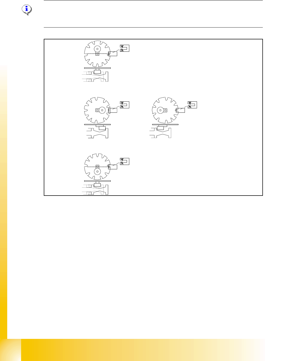
6.2.3 Initialize Valve Drive at Reject Position which is not use on HF machine
Note
Initializtion of the valve drive it‘s only important that the plunger has a defined position and the star
axis can drive easlly.
Fig. 6.2 - 3 Initialize valve drive at reject position
Key
(6) home position, initial positon. Give way free for Star axis movement. Drawing show 2 possible
positions of the plunger
(7) 2a. is switching to vacuum,Vacuum value "Nozzle open"
2b. is switching to air kiss, Vacuum value "Nozzle closed"
(8) counter position to initial position. Give way free for Star axis movement.
– The stepper motor of the valve drive is turned to the home position. The stepper motor runs
and the light barrier on the cam disk sets the end signal.
– Because of the special shape of the cam disk the stepper motor is able to recognize the home
position (1.).
1
2a
2b
3
1 - 17
Student Guide SIPLACE HF/HF3
Edition 09/2005 6 Collect &Place-Head / DLM2
17
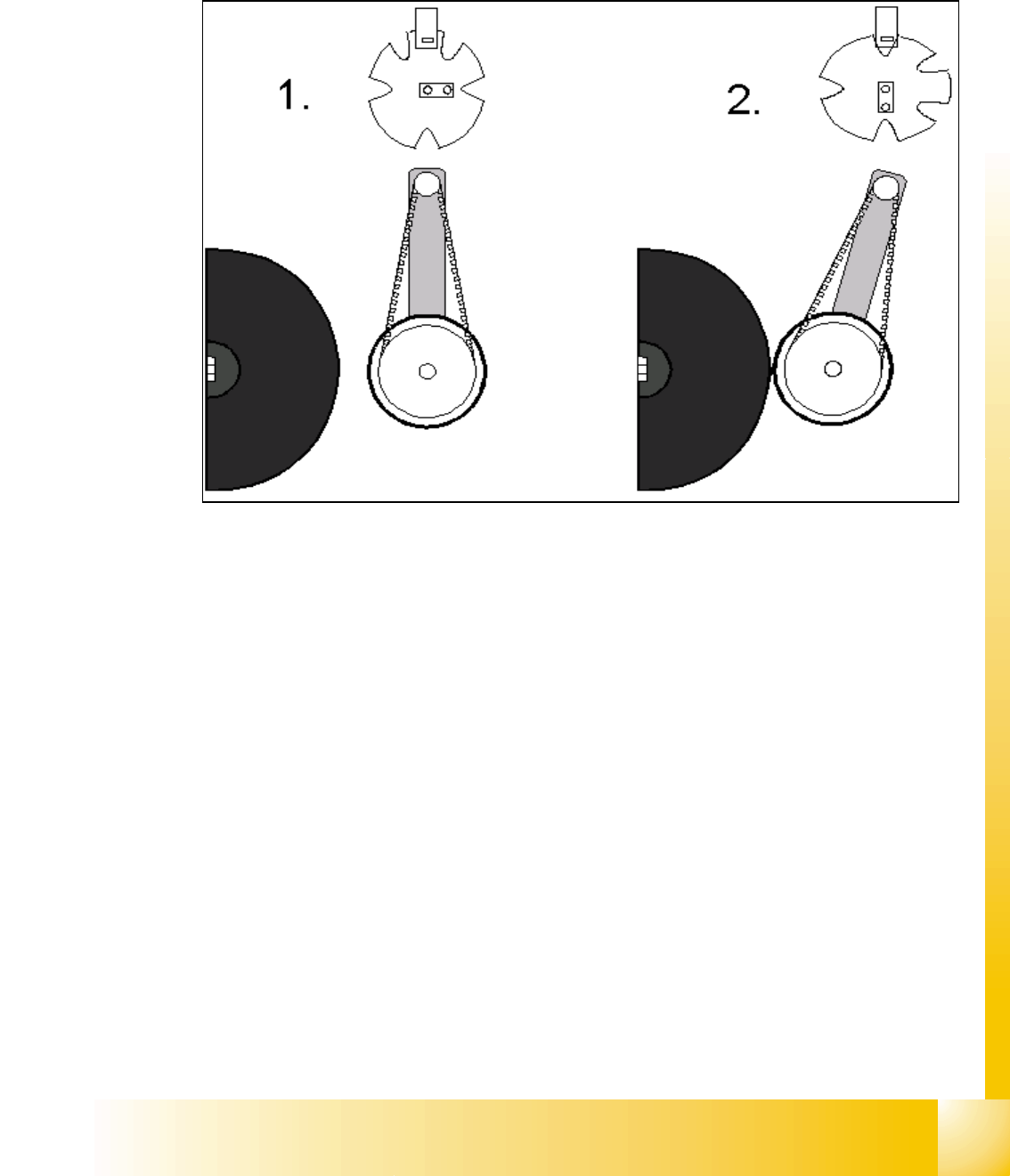
6.2.4 Initialize Valve Drive at DP-station
The function of the stepper motor at the DP station, with the aid of an eccentric movement, is to
contact the sleeve and rotate the components and nozzles to the correct position via the DP axis.
Fig. 6.2 - 4 Initialize stepper motor at DP-station
Key
(1) Home position DP drive around 1 mm away from segment
(2) Engaged position DP drive at segment
– The stepper motor of the valve drive is turned to the home position. The stepper motor runs
and the light barrier on the cam disk sets the end signal.
– Because of the special shape of the cam disk the stepper motor is able to recognize the home
position.
(DP german abbrev. for turning sleeve)
1 - 18
Student Guide SIPLACE HF/HF3
6 Collect &Place-Head / DLM2 Edition 09/2005
18
6.2.5 Preparing Z-axis Reference Run
Fig. 6.2 - 5 Preparing Z-axis reference run (6 C&P head)
The Z-axis runs to uppermost end stop. When stand still is detected the Z-axis runs down by 27
digits with reduced force.
This Z-axis position with reduced force enables the placement star to move into reference posi-
tion.
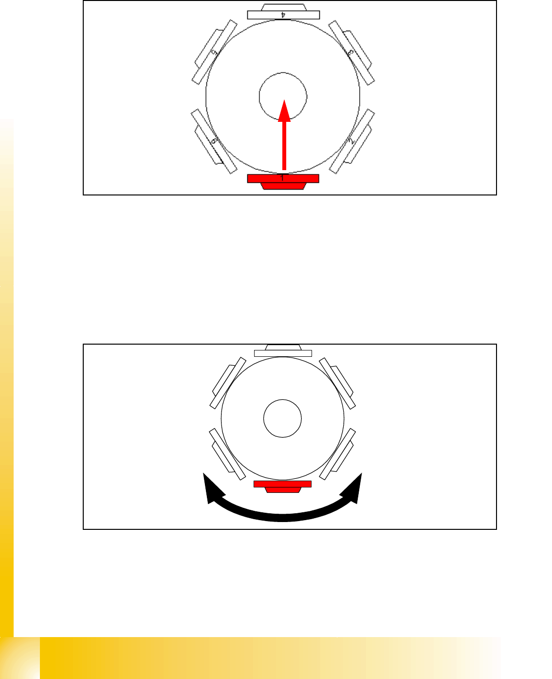
6.2.6 Reference Run at Star-Axis
Fig. 6.2 - 6 Reference run at star-axis
The star-axis turns counter clockwise to zero point pulse of the incremental shaft encoder. The
zero point correction is loaded. The star-axis turns clockwise (according the zero point correction)
until the position counter shows 0 digit.
Segment number 1 is now in pick-up / placement position.
4
1
5
2
3
6