SG_FSE_SiplaceHF_HF3_00193901-05_eng.pdf - 第225页
1 - 25 S tudent Guide SIPLACE HF/HF3 Edition 09/2005 6 Colle ct &Place-Head / DLM2 25 6.3.4 PCB position recognition ce ntering of the PCB fiducials Fig. 6.3 - 4 PCB position recogniti on centering of the PCB fiducia…
1 - 24
Student Guide SIPLACE HF/HF3
6 Collect &Place-Head / DLM2 Edition 09/2005
24
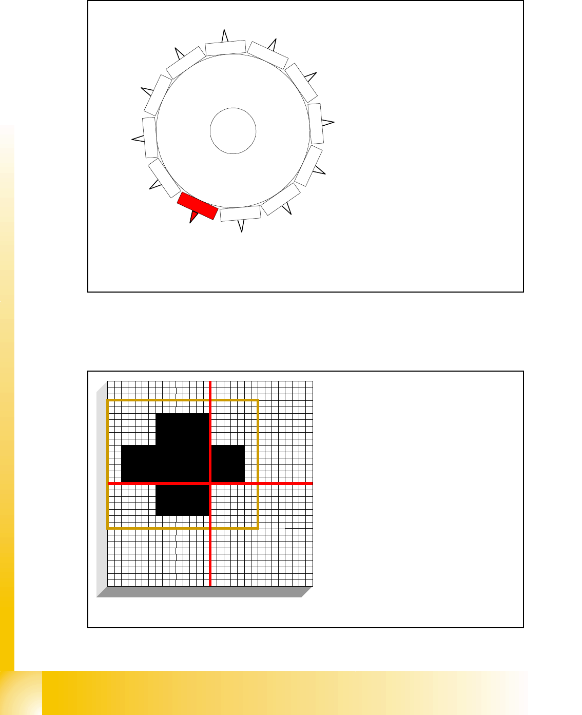
6.3.2 12 nozzle Collect & Place head in home position 15
°
Fig. 6.3 - 2 12 nozzle Collect & Place head in home position
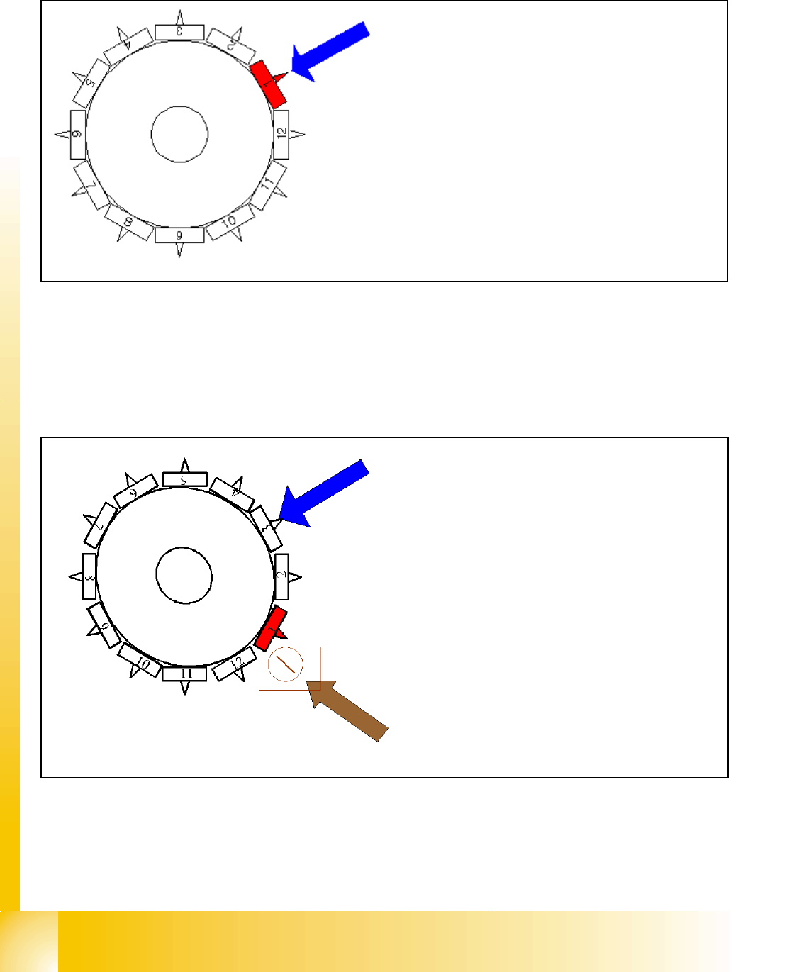
6.3.3 PCB position recognition run to the PCB nominal position
Fig. 6.3 - 3 PCB position recognition run to the PCB nominal position
1
2
1
1
1
0
9
8
7
6
5
1
2
3
4
the Star-axis is turned to home position.
When the X- and Y-axis is in waiting position
Star position:
15 degrees
Digit: 15.000
1 degree is equivalent to 1000 digits
The fiducial is expected at this nominal posi-
tion. The PCB camera is moved from waiting
position to this fiducial position.
– PCB position recognition is done before
the first component is picked up.
– The gantry axes move the PCB camera to
the theoretical fiducial position. The cam-
era takes the picture of the first fiducial
and the vision system calculates the cen-
ter position.
1 - 25
Student Guide SIPLACE HF/HF3
Edition 09/2005 6 Collect &Place-Head / DLM2
25
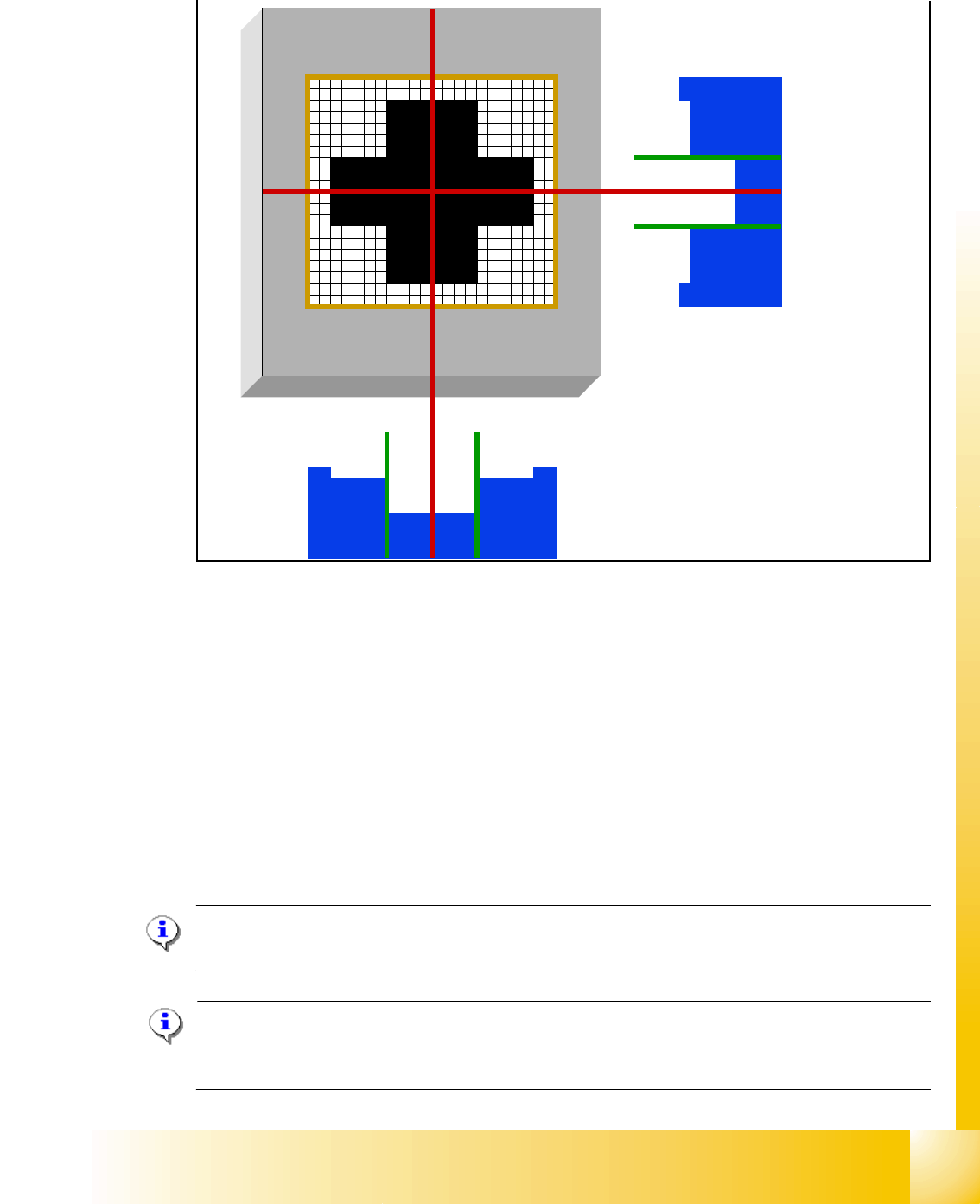
6.3.4 PCB position recognition centering of the PCB fiducials
Fig. 6.3 - 4 PCB position recognition centering of the PCB fiducials
The centered fiducial define now theactual position of the board.
– The camera takes the picture of the second fiducial and the vision system calculates the center
position of this picture.
– The 2nd calculation is the deviation between nominal and calculated fiducial position.
– All board fiducials are optically centered with this procedure.
– This data is sent to the machine controller
– The correction values are calculated for the X, Y and the angular position of the PCB .
– Now the gantry axes move the placement head to the first pick up position
Please Note If synthetic fiducials are used nothing change on the described sequence. The only
thing what change: the Inkspot recognition could be done after fiducial recognition.
Please Note:
The PCB position recognition is carried out with both gantries in the placement area (with SW
505). 6
1 - 26
Student Guide SIPLACE HF/HF3
6 Collect &Place-Head / DLM2 Edition 09/2005
26
6.3.5 Turn nozzle 1 to Pick up angle (0° or 90°)
Fig. 6.3 - 5 Turn nozzle 1 to Pick up angle (0° or 90°)
The remaining nozzles on the head are turned to their pick up angles as the star steps
6.3.6 Check nozzle length for component recognition
Fig. 6.3 - 6 Check the nozzle length for component recognition in the comp. sensor
Star position 240°
– The star-axis is turned to 240° (equivalent to
240000 Digits). Now the nozzle 1 is in DP-station.
– DP-station swivels in and the DP-axis controller
system turns the rectangular nozzle to their 0° or 90
° Pick up angle (Standard pick up angle´s).
– When the nozzle is in position the end signal is trig-
gered and the DP-station swivels off.
Component sensor (option) measures at
315°:
– the component sensor measures the noz-
zle length.
– The measured length before pickup is ver-
ified with the reference length
– A length difernce of +0.15 mm or -0.1 mm
generate a error message and gantry
move immediatelly to Service position.
– The measurement in the component sen-
sor happens at full movement of the star
axis -"on the fly"- .