SG_FSE_SiplaceHF_HF3_00193901-05_eng.pdf - 第231页
1 - 31 S tudent Guide SIPLACE HF/HF3 Edition 09/2005 6 Colle ct &Place-Head / DLM2 31 6.3.15 Placing 6th component Fig. 6.3 - 15 Placing 6th component 6.3.16 Placing 7th Component Fig. 6.3 - 16 Placing 7th component …
1 - 30
Student Guide SIPLACE HF/HF3
6 Collect &Place-Head / DLM2 Edition 09/2005
30
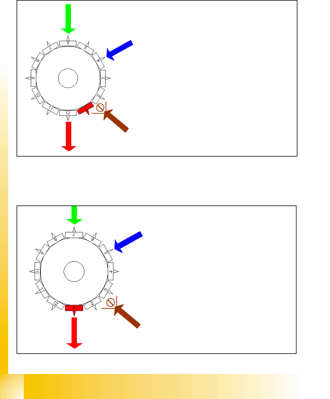
6.3.13 Pick up 12th component
Fig. 6.3 - 13 Pick up 12th component
6.3.14 Placing 1st component
Fig. 6.3 - 14 Placing 1st component
Star position 330°
– Vision system: optical centering of the 6th com-
ponent
– DP-station: turn 4th component to the placement
angle
– pick up / placement station: pick up 12th compo-
nent
– communication with the component table: acti-
vate tape cutter
– synchronization: after picking the 12th compo-
nent this gantry is waiting for placement enable
signal from MC.
– component sensor:during the next Star step the
comp. presence or comp. height at segment 2 is
measured.
Star position 0°
– Vision system: optical centering of the 7th com-
ponent
– DP-station: turn 5th component to the place-
ment angle
– pick up / placement station: place 1st compo-
nent
– component sensor (option) during the next Star
step the comp. presence or comp. height at seg-
ment 3 is measured.
The process continues for the remaining nozzles
1 - 31
Student Guide SIPLACE HF/HF3
Edition 09/2005 6 Collect &Place-Head / DLM2
31
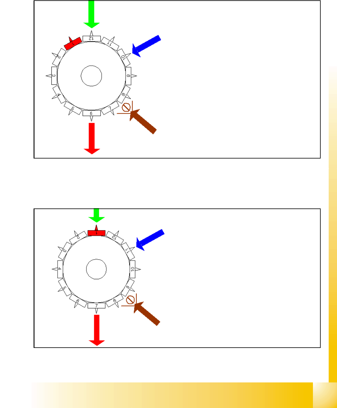
6.3.15 Placing 6th component
Fig. 6.3 - 15 Placing 6th component
6.3.16 Placing 7th Component
Fig. 6.3 - 16 Placing 7th component
Star position 150°
– Vision system: optical centering of the 12th compo-
nent
– DP-station: turn 10th component to the placement
angle
– pick up / placement station: place 6th component
– synchronization: communication with the MVS for
the optical centering of component´s on the other
gantry.
– component sensor: during the next Star step the
comp. presence or comp. height at segment 8 is
measured.
St
ar pos
iti
on
180°
– Vision system: optical centering of the 1st component
on the other gantry
– DP-station: turn 11th component to the placement an-
gle
– pick up / placement station: place 7th component
– component sensor: during the next Star step the
comp. presence or comp. height at segment 9 is mea-
sured.
1 - 32
Student Guide SIPLACE HF/HF3
6 Collect &Place-Head / DLM2 Edition 09/2005
32
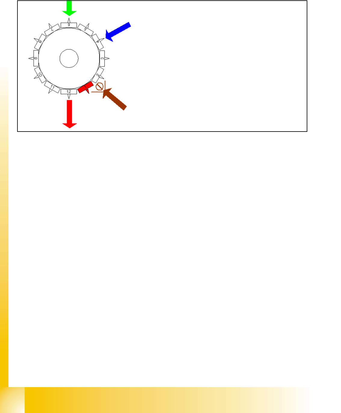
6.3.17 Placing 12th Component
Fig. 6.3 - 17 Placing 12th component
6.3.18 Pick up and placement cycle for the next components...
– After all the components of the first head cycle are placed onto the board, the gantry axes move
the placement head to the pick up position of the next pick up cycle.
– The next pick up cycle for components 13 to 24 (7 to 12 for 6 nozzle head) is executed.
– And so on and so on..... If necessary the machine executes repair cycles.
6.3.19 Segment with a „defective component“
If the optical centering of a component fails (Ident.error) or the vacuum check before placement
fails (Vacuum error) alternatively comp.check / height measurement at the comp. sensor fails the
component is not placed and remain on the nozzle;
– the turning station turn now this nozzle to the pick up angle of the new component when this
segment is in turning position.
If this segment is in pick up position:
– the reject procedure is activated
– X-/Y-axes move from feeder pos. to their reject position
– the component is rejected by an air kiss to comp. reject box
– X-/Y-Axes return to feeder position
– the new component is picked
This rejected component is placed after all placement cycles by a „repair cycle“.
Star position 330°
– Vision system: optically centering of the 6th
component on the other gantry
– DP-station: turn 4th nozzle to the pick up angle
for the next pick up cycle.
– pick up / placement station: place 12th compo-
nent
– synchronization: after placing the 12th compo-
nent of this gantry placement enable signal is re-
turned to MC.
– component sensor: during the next Star step the
nozzle length at segment 2 is measured.