SG_FSE_SiplaceHF_HF3_00193901-05_eng.pdf - 第240页
1 - 40 S tudent Guide SIPLACE HF/HF3 6 Collect &Place-He ad / DLM2 Edition 09/2005 40 – T his height is r educed by 1.23 mm a nd saved f or the actu al contactless picku p height. Default pickup sequence :S tart gant…
1 - 39
Student Guide SIPLACE HF/HF3
Edition 09/2005 6 Collect &Place-Head / DLM2
39
6.3.28.1 Advantage of special mode "slow start upwards" after pick up
This "slow start upwards" offer you:
– increased pickup reliability with all nozzles and heavy or exotic components. At Z-axis travel
time for the first mm the vacuum increase in our segment to the maximum. This make the max-
imum grip between component and nozzle .
– No Danger of additional head pollution!
– There is a delay of 20 ms compared to the standard pickup cycle.
– Attention:Do
NOT program ’creep start upwards’. This take more than 100 ms time without
any advantages on the vacuum.
– For special constructions of feeder you have the change to programm a additional waiting time
down at the feeder. Siemens feeder at the moment do
NOT need this feature.
Independent to this special mode programming of 503 SW the acceleration of the Z-Axis can be
reduced to any value. (waist additional time!)
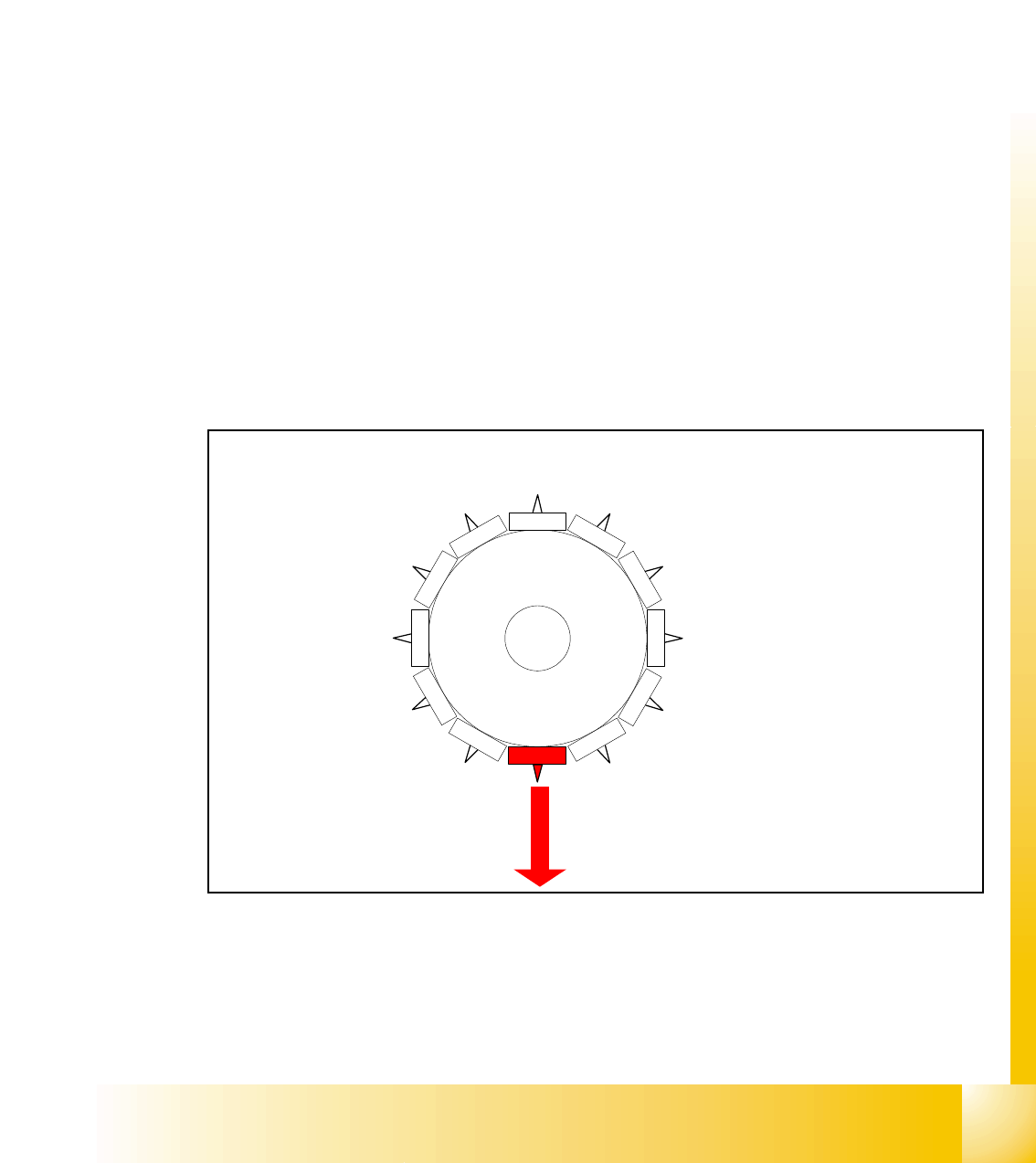
6.3.29 Special mode "contact less pickup" Z-axis downward
At LRU/LRL 503 or Siplace Pro you can activate "contactless pick up" in the GF-File ONLY for
SC/MC 503 stations and higher.
Fig. 6.3 - 26 Z-axis downwards with special mode “contactless pick up”
At the very first pickup from a comp. track where contactless pickup is programmed is:
– with increased force the pick up height calibrated. Z-Axis run to the mechanical end stop in
the feeder.
1
2
1
1
10
9
8
7
6
5
1
2
3
4

1 - 40
Student Guide SIPLACE HF/HF3
6 Collect &Place-Head / DLM2 Edition 09/2005
40
– This height is reduced by 1.23 mm and saved for the actual contactless pickup height.
Default pickup sequence
:Start gantry axes to the pick up position next feeder & communication to component table:
– start signal to Gantry axes
– Next feeder signal / this opens feeder flap
end signal X-, Y-, Star-axis:
– end signal Star-axis
– Vacuum check: Segment sealed? before pick up
– X / Y end signals existing
Z-Axis starts:
– Z-axis starts positioning downward in absolute positioning mode.
light barrier (LB) above :
– enables LB bottom but this is not activated
Axis controller trigger:
– end signal positioning Z-axis downwards
Machine controller switch with end signal positioning Z-axis down:
- valve drive to vacuum
6.3.29.1 Advantage of special mode "contactless pick up"
This "contactless pick up" offer you:
– no touch to the component feed module and therefor no movement of components - no jump-
ing of components at pick up area.
– increased pickup reliability for very light and easy "jumping" components. The nozzle float ap-
proximately 0.1 mm above the component and suck it out of the component pocket.
– No delay compared to the standard pickup cycle.
– No additional polution in the head.
– No restriction on feeder or component types. The nozzle have to have only enough suction
force for the component.
The first component from the learning sequence is rejected to the reject bin (SC/MC 505 or
patched SC/MC-version).
1 - 41
Student Guide SIPLACE HF/HF3
Edition 09/2005 6 Collect &Place-Head / DLM2
41
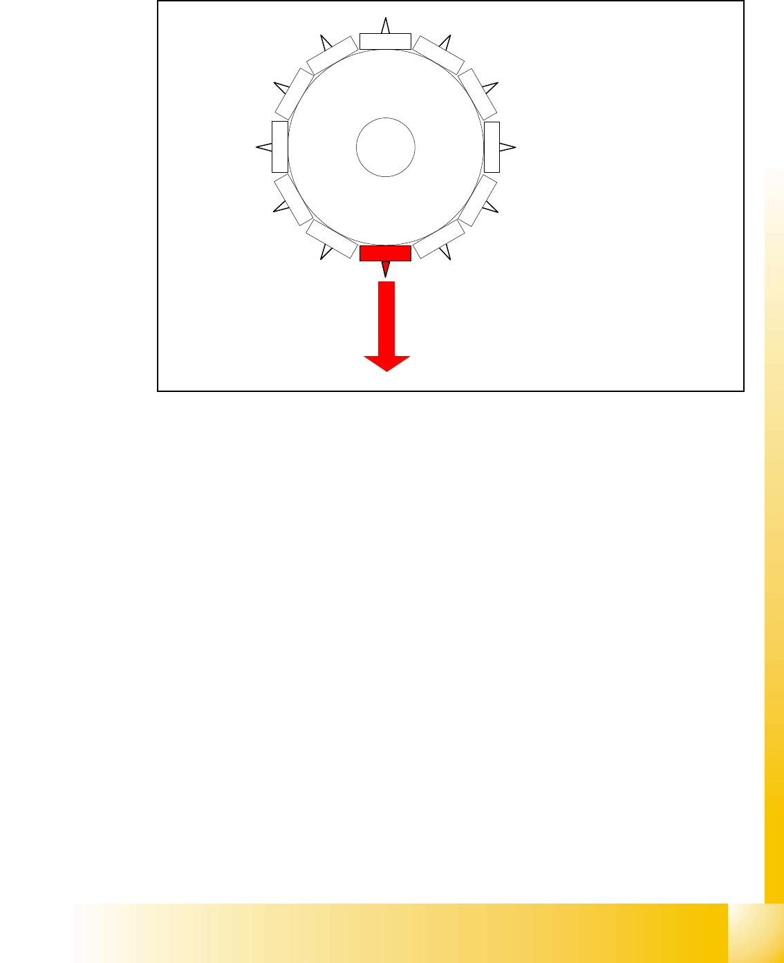
6.3.30 Placing component detailed: Z-axis downwards
Fig. 6.3 - 27 Placing component detailed: Z-axis downwards with light barrier mode
The placement force is defined by the spring in the sleeve ~2.4 N at 12 nozzle head
End signal X-, Y-, Star-axis:
– all 3 end signal available
– vacuum check before placement is executed (alternatively the component check in the
comp.sensor).
– component on the nozzle?
Z-axis starts:
– Z-axis positioning downward
LB above switches:
– solenoid air kiss ON
– enable LB bottom
LB bottom switches:
– End signal positioning downward;
– valve drive, pick up- placement position, to air kiss
1
2
1
1
10
9
8
7
6
5
1
2
3
4