SG_FSE_SiplaceHF_HF3_00193901-05_eng.pdf - 第247页
1 - 47 S tudent Guide SIPLACE HF/HF3 Edition 09/2005 6 Colle ct &Place-Head / DLM2 47 6.3.35.1 Advant age of special mode " W aiting time at placeme nt" This expen ded function " W aiting time a t plac…
1 - 46
Student Guide SIPLACE HF/HF3
6 Collect &Place-Head / DLM2 Edition 09/2005
46
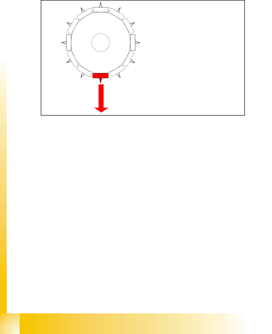
6.3.35 Special mode: Z-Axis downwards with waiting time at placement
Fig. 6.3 - 32 Special mode: Z-Axis downwards with waiting time at placement
End signal X-, Y-, Star - Axis:
– all 3 end signal available
– vacuum check "before placement" is executed component on the nozzle?
(or signal from component sensor)
Z-axis start:
– Z -Axis positioning downward positioning mode -absolute-
LB above switch:
– Electro magnetic valve air kiss ON
– enable LB bottom
Light barrier bottom trigger:
– End signal positioning downward
– valve drive, pick up- placement position, to air kiss
Special mode" Waiting time down":
– End signal Z-axis downward the waiting time will be started of the MC
– After the waiting tim is the air kiss measured
– Positioing mode for Z-axis upwards is started
1
2
11
10
9
8
7
6
5
1
2
3
4
1 - 47
Student Guide SIPLACE HF/HF3
Edition 09/2005 6 Collect &Place-Head / DLM2
47
6.3.35.1 Advantage of special mode " Waiting time at placement"
This expended function "Waiting time at placement " could you use:
– with each special mode for the Z-Axis combined.
This expended function "Waiting time at placement " could you use:
– a Waiting time at placement height could be programmed to press components into solder
paste or BareDies into conductive glue.
– In such a way, press very big components into the solder paste with placement force that all
pins contact the solder paste.
– A delay time compared to the standard placement cycle depend of the programmable time.
Caution!
The Z-Axis in this special mode " Waiting time at placement" is down and now you press the emer-
gency stop button or open the cover the Z-Axis will stay down!!
Please Note:
The same special mode is possible for the pick up procedure, but it is not neccessary for the fee-
der. 6
6.3.36 Optical nozzle scanning
1. After placing the first board the nozzle scanning is activated:
– All nozzles mentioned in SCANPARA.MA (SC/MC 407) (SC/MC 502/503 in data base) are
measured by the component camera (nozzles like 901,904,911,914,925).
– If there is any bright spot on with a defined size and brightness the machine displays “nozzle
segment... worn out or polluted”.
2. Tiny nozzles may touch the solder paste or the glue because of component shift and the min-
imum component height.
3. The number of components per segment (number of head cycles) after which the next nozzle
scanning is executed should be adjusted to customers process needs. This check is always
performed after the PCB processing is complete.
4. Another option:
– This is not a fatal error and the machine only displays the error and does not stop.

1 - 48
Student Guide SIPLACE HF/HF3
6 Collect &Place-Head / DLM2 Edition 09/2005
48
6.3.37 Description air kiss control
Air kiss control at placement: 6
Value “0” mean the blast air valve don‘t switch on.
(1) Value “1-50” mean blast air valve is switched OFF when stepper motor valve drive start to
move.
(2) Value “51-150” mean blast air valve is switched OFF when stepper motor valve drive moved
for 90 degree.
(3) Value. “151-255 mean blast air valve is switched OFF when stepper motor valve drive moved
for 180 degree.
Or at light barrier top.
No value “----” (from converting 501/502 to 503 format) mean same mode than
(3) (existing
standard).
Air kiss control at return component! (not reject) 6
(4) Value and description like (1)
(5)
Value and description like (2)
(6)
Value. “151-255” mean blast air valve is switched OFF when stepper motor valve drive moved
for 180 degree.
Please Note
More Information about the air kiss control see chapter C&P head with (Flow chart).