SG_FSE_SiplaceHF_HF3_00193901-05_eng.pdf - 第252页
1 - 52 S tudent Guide SIPLACE HF/HF3 6 Collect &Place-He ad / DLM2 Edition 09/2005 52 6.4.1.3 CAN Processorboard 16 Bit The 16 BIT CAN Processo r are use for different funct ions of the followin g units: – Visionboar…
1 - 51
Student Guide SIPLACE HF/HF3
Edition 09/2005 6 Collect &Place-Head / DLM2
51
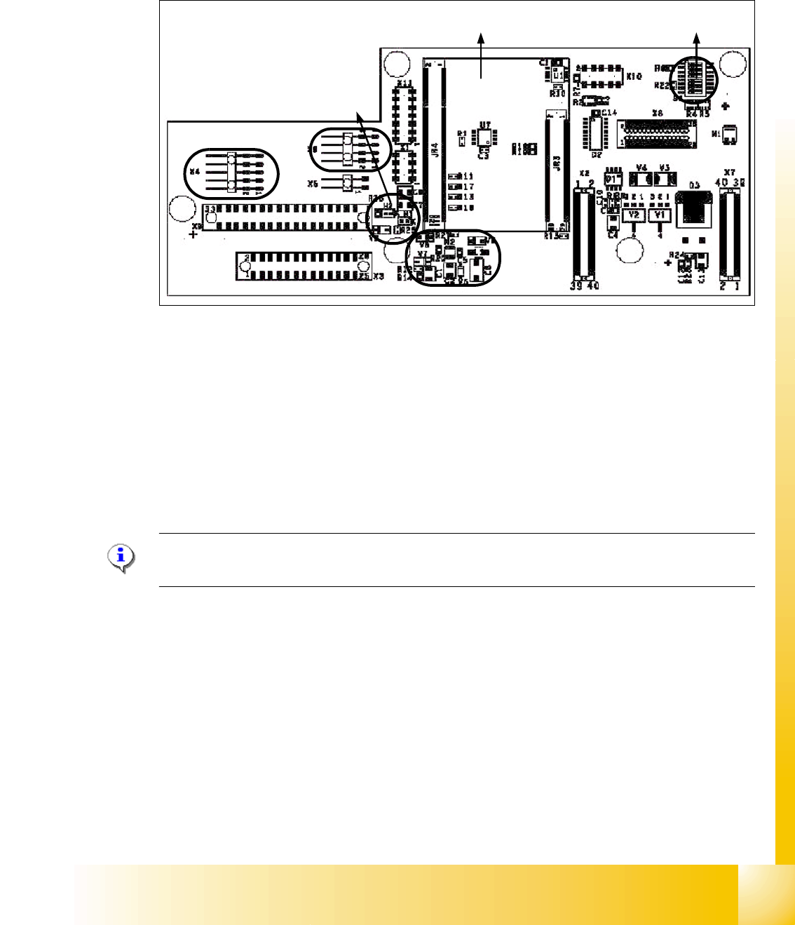
6.4.1.2 Vision board (analog)
The vision board are connect on the top of the head interface. That board is used on the gantry
with a C&P head and TWIN-head.
Fig. 6.4 - 2 Vision board
1. Connector illumination PCB camera
2. Connector PCB camera
3. LED‘s P15V - 15Volt / Vcc - Power supply Vision board
4. DIP Switch
5. CAN Prozessor 16 Bit (additional board on the Visionboard)
6. DC/DC Converter 15 --> 5V for Visionsystem.
Please Note:
The DIP Switch configuration for the gantry is decribed in chapter gantry .
4
5
1
3
2
6
1 - 52
Student Guide SIPLACE HF/HF3
6 Collect &Place-Head / DLM2 Edition 09/2005
52
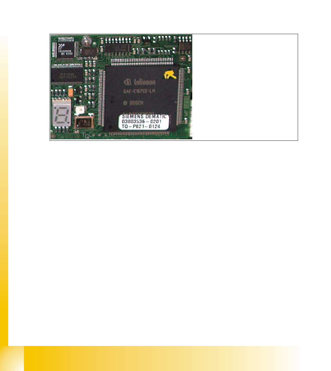
6.4.1.3 CAN Processorboard 16 Bit
The 16 BIT CAN Processor are use for different functions of the following units:
– Visionboard, communication and control via the ICOS system.
– Mainboard Twin head, control the vacuumgenerator.
– Visionboard for the stationary IC (FC) - Camera, communication and control via the ICOS
system in sector 2 and 4.
Fig. 6.4 - 3 16 Bit Processor
Description 7 Segment display ( Standard mode " . " flashed):
– After switch ON the machine appears " 0 " on the display
– Display " b " Bios is started.
– Display flash alternately "b" and " . " --> none Application available or can not started.
– Display " -I " und " I- " Application is loaded and now starts.
– The " . " on the display flashed.
(1) 7 Segment display
(2) LED red at the bei manual RESET
on the Processors
(3) 16 Bit Processor
2
3
1
1 - 53
Student Guide SIPLACE HF/HF3
Edition 09/2005 6 Collect &Place-Head / DLM2
53
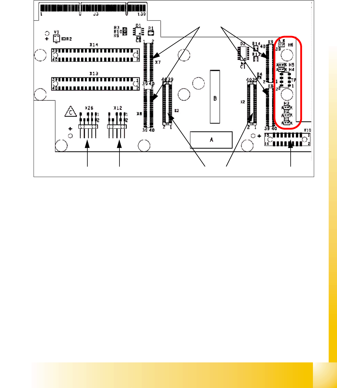
6.4.1.4 Headadapter for 6/12 C&P head
At the head modularity we can use the same head adapter for the 6 and 12 segment C&P heads.
The head adapter must be exchanged if you mounting the Twin head.
Fig. 6.4 - 4 Headadapter for 6/12 C&P head
1. X6 -X9 Connector for CAN Prozessor-board’ 80C515C 8Bit
2. X2/X3 Connector for the stepping motor board
3. X10 Connector vacuum board
4. X12 Dp station (motor, track signale)
5. X26 Option component sensor
6. X13/14 connector for the flat cable to the intermediate distribution boardr
7. Connector to the headinterface
Description LED‘s: 6
– LZOS Light barrier Z-axis upper stop
– LZUS Light barrier Z-axis down position
– LSM Stepper motor board not connected
– LSZD Light barrier Swivel in for turning at DP-station
– LSVZ Light barrier Vacuum / air kiss Z-axis
– LSVA Light barrier Vacuum / air kiss reject position
1
2
45
3
6
7
LED‘S