SG_FSE_SiplaceHF_HF3_00193901-05_eng.pdf - 第257页
1 - 57 S tudent Guide SIPLACE HF/HF3 Edition 09/2005 6 Colle ct &Place-Head / DLM2 57 6.4.1.9 SP_12 Digit al intermediate distribution board (00330648-05) 6 Fig. 6.4 - 8 SP6_12 intermediate distribution board (Pictur…

1 - 56
Student Guide SIPLACE HF/HF3
6 Collect &Place-Head / DLM2 Edition 09/2005
56
6.4.1.8 Status "7 Segment display"
The status of the PROCESSOR BOARD 80C515C FW is indicated on the 7-segment display.
Normal status on the diplay is: Display shows " 0 " and the " . " flashed slowly.
7 Segment
Display Description status prozessor board
display 0 The FW has the status OK.
display 1
CAN telegram cannot be sent. This status occurs if the 80C515C PROCES-
SOR BOARD cannot issue its start telegram after the station is switched on.
What to do: There is an error in the CAN-BUS wiring or
on the COM module in the control unit.
display 2
FW error: CAN-BUS receive buffer overflow. Command for 80C515C PRO-
CESSOR BOARD is lost.
What to do: HW reset of the 80C515C PROCESSOR BOARD
display 3
The CAN-BUS controller has the status ERROR PASSIVE.
CAN-BUS transmission errors have occurred.
What to do: After a number of successful transmissions,
this error disappears automatically.t
display 4
The CAN-BUS controller has the status BUS-OFF. CAN-BUS transmission
errors have occurred that have led to the shutdown of the CAN controller.
What to do: HW reset of the 80C515C PROCESSOR BOARD
display 5
The 80C515C PROCESSOR BOARD has received a message instead of a
command. This occurs with the SIPLACE HS50 when two 80C515C PROCES-
SOR BOARDS have the same HW address.
What to do: Use jumper to correct gantry address.
display 6
The power-fail signal is activated. This occurs if the power-fail signal is active
when the station starts up.
What to do: Check the power-fail wiring.
display F
Other status (occurs only in the event of a firmware error) For example: no
valid command in BIOS
display any
C0005 HW problem
– Check the RESET signal for the 80C515C PROCESSOR BOARD.
– uP not running, HW fault (possibly a cold soldered joint)
display A
At initialization: Transition from BIOS to the application module
display b
At startup: Head processor remains in the BIOS (ready to receive BIOS com-
mands, e.g. download)
1 - 57
Student Guide SIPLACE HF/HF3
Edition 09/2005 6 Collect &Place-Head / DLM2
57
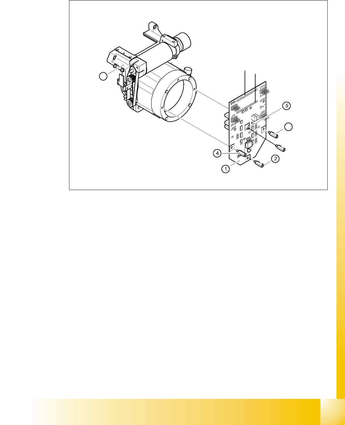
6.4.1.9 SP_12 Digital intermediate distribution board (00330648-05)
6
Fig. 6.4 - 8 SP6_12 intermediate distribution board (Picture DLM 1)
Legend
The intermediate distribution board (1) is fixed to the front part (4) with four spacer bolts (items 2,
3,4 and 5). The cover of the intermediate distribution board is fixed with push buttons.
6
Two 40-pin ribbon cables run from plug X1 and X2 on the intermediate distribution board to socket
X14 / X13 on the head board.
6
6
(1) Intermediate distribution board (2) M3x10 spacer bolt
(3) M3x10 spacer bolt (4) M3x10 spacer bolt
(5) M3x10 spacer bol (6) Front part of the collect&place head
3
6
X 1
X 2
1 - 58
Student Guide SIPLACE HF/HF3
6 Collect &Place-Head / DLM2 Edition 09/2005
58
6
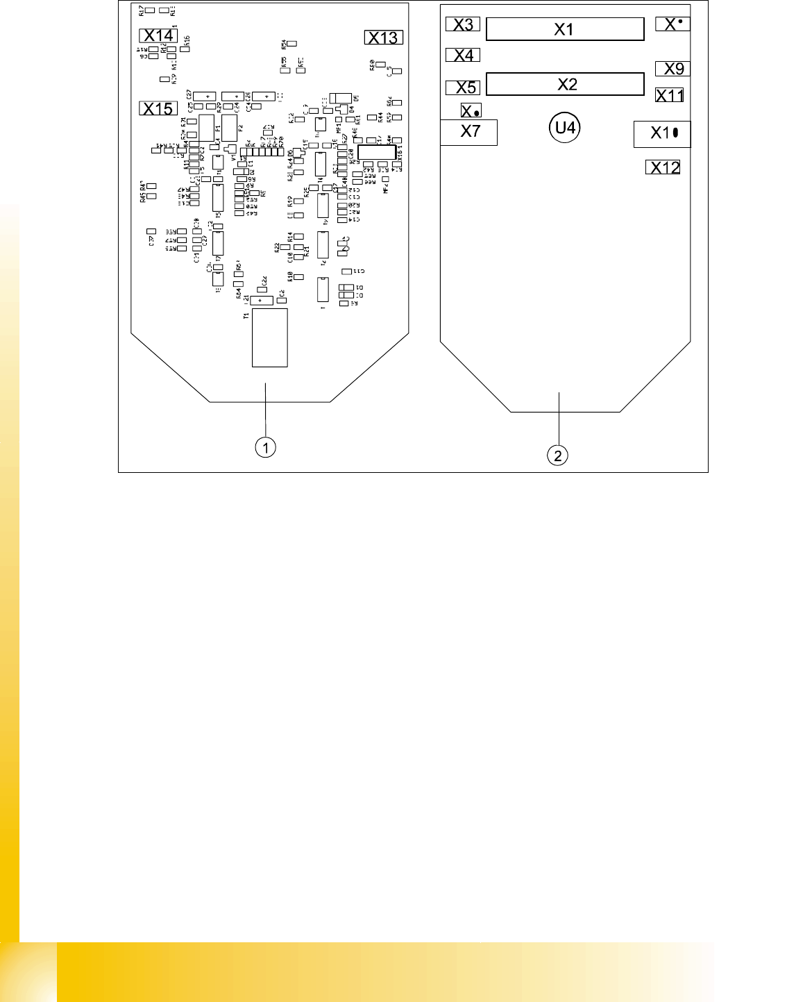
Abb. 6.4 - 9 Intermediate distributor - position of the sockets
Legende
The following supply voltages and signals are routed by the intermediate distribution board to the
individual placement head modules or to the head board:
6
Plug X1, 40-pin 6
Connected to plug X14 on the head board 6
– Voltage supply, tacho and track signals for the Z-axis drive
– Signal from light barrier "Z-axis in top position"
– Signal from light barrier "Z-axis in bottom position" (sensor stop signal)
– Control signal for the forced air valve
– Supply voltage + 5VDC, ± 15VDC
– Reference point signal for the DP-axis
– Track signals for the DP-axis
(1) Front of the intermediate distributor (2) Back of the intermediate distributor
U4 Pressure sensor for air kiss
X16