SG_FSE_SiplaceHF_HF3_00193901-05_eng.pdf - 第258页
1 - 58 S tudent Guide SIPLACE HF/HF3 6 Collect &Place-He ad / DLM2 Edition 09/2005 58 6 Abb. 6.4 - 9 Inte rmediate distributor - position of the sockets Legende The following supply volt ages and signals are routed b…
1 - 57
Student Guide SIPLACE HF/HF3
Edition 09/2005 6 Collect &Place-Head / DLM2
57
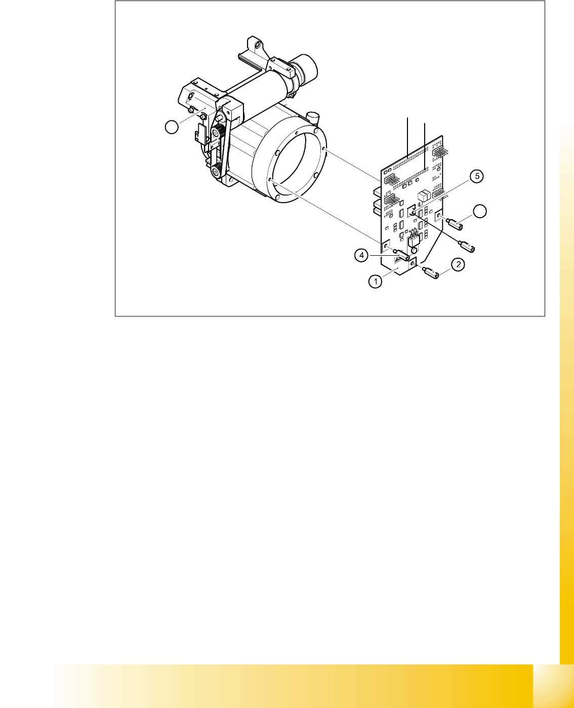
6.4.1.9 SP_12 Digital intermediate distribution board (00330648-05)
6
Fig. 6.4 - 8 SP6_12 intermediate distribution board (Picture DLM 1)
Legend
The intermediate distribution board (1) is fixed to the front part (4) with four spacer bolts (items 2,
3,4 and 5). The cover of the intermediate distribution board is fixed with push buttons.
6
Two 40-pin ribbon cables run from plug X1 and X2 on the intermediate distribution board to socket
X14 / X13 on the head board.
6
6
(1) Intermediate distribution board (2) M3x10 spacer bolt
(3) M3x10 spacer bolt (4) M3x10 spacer bolt
(5) M3x10 spacer bol (6) Front part of the collect&place head
3
6
X 1
X 2
1 - 58
Student Guide SIPLACE HF/HF3
6 Collect &Place-Head / DLM2 Edition 09/2005
58
6
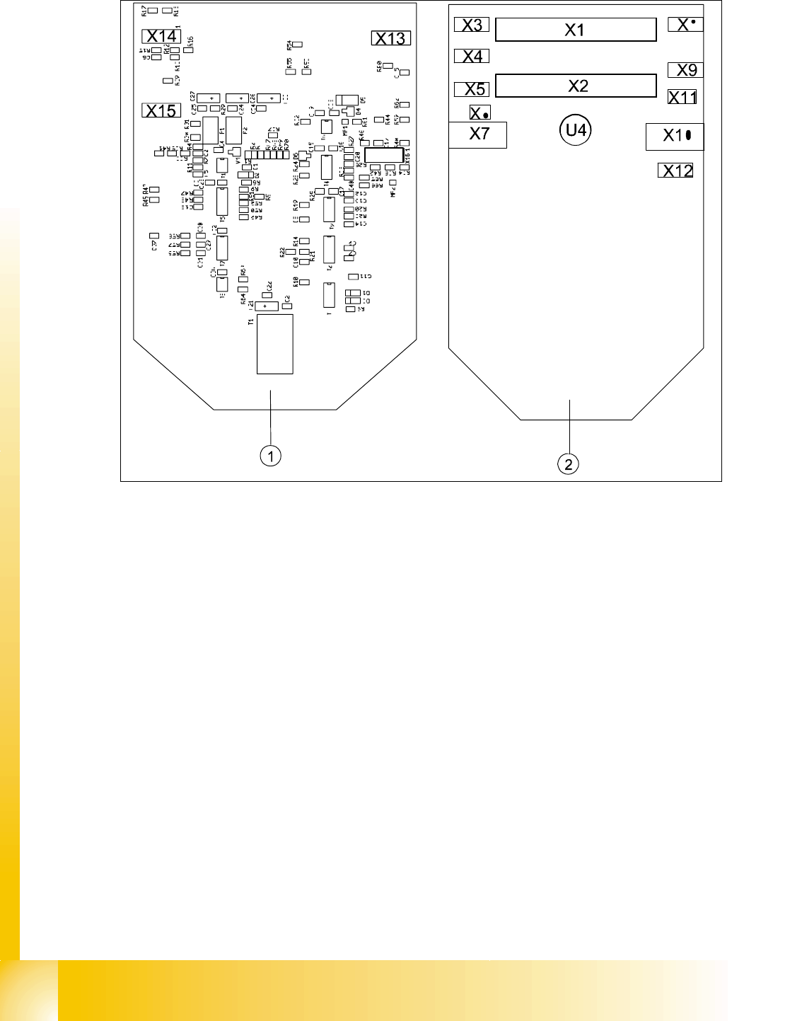
Abb. 6.4 - 9 Intermediate distributor - position of the sockets
Legende
The following supply voltages and signals are routed by the intermediate distribution board to the
individual placement head modules or to the head board:
6
Plug X1, 40-pin 6
Connected to plug X14 on the head board 6
– Voltage supply, tacho and track signals for the Z-axis drive
– Signal from light barrier "Z-axis in top position"
– Signal from light barrier "Z-axis in bottom position" (sensor stop signal)
– Control signal for the forced air valve
– Supply voltage + 5VDC, ± 15VDC
– Reference point signal for the DP-axis
– Track signals for the DP-axis
(1) Front of the intermediate distributor (2) Back of the intermediate distributor
U4 Pressure sensor for air kiss
X16

1 - 59
Student Guide SIPLACE HF/HF3
Edition 09/2005 6 Collect &Place-Head / DLM2
59
Plug X2, 40-pin 6
Connected to plug X13 on the head board 6
– Voltage supply and track signals for the star-axis drive
– Reference point for the star-axis
– Analog forced air pressure value
– Supply voltages + 5VDC, ± 15VDC, + 24VDC
Plug X3, 10-pin 6
Connection for the Z-motor and Z-tacho signal (Tacho signal is not use on the HF-machine) 6
Plug X4, 10-pin 6
Connection for the Z-axis track signals 6
Plug X5, 10-pin 6
Connection for the star motor 6
Plug X6, 6-pin 6
Connection for the forced air valve 6
Plug X7, 10-pin 6
Connection for the DP-axis track signals 6
Plug X10, 10-pin 6
Connection for the "Z-axis up" signal 6
Plug X11, 8-pin 6
Connection for the light barrier "Z-axis down" signal (sensor stop signal) 6
Plug X12, 10-pin 6
Connection for the star-axis track signals 6
Plug X13, 10-pin 6
Test connection for the Z-axis track signals
Plug X14, 10-pin 6
not used
Plug X15, 10-pin 6
Test connection for the Star-axis track signals
Plug X15, 10-pin 6
Test connection for the Dp-axis track signals