SG_FSE_SiplaceHF_HF3_00193901-05_eng.pdf - 第269页
1 - 69 S tudent Guide SIPLACE HF/HF3 Edition 09/2005 6 Colle ct &Place-Head / DLM2 69 6.4.9 Determination of Zero Po int Correction St ar-Axis C&P Head Fig. 6.4 - 18 Flow chart zero point correction Men u e C &am…
1 - 68
Student Guide SIPLACE HF/HF3
6 Collect &Place-Head / DLM2 Edition 09/2005
68
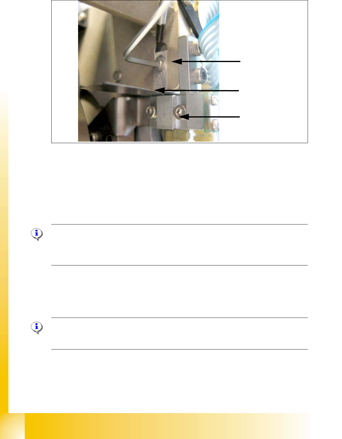
Fig. 6.4 - 17 Z-Limit stop check and adjust
➠ Loosen the screw of the Z limit stop.( Fig. 6.4 - 17)
➠ Clamp a 15/100 mm feeler gauge between the Z limit stop and the clamp. Push the Z limit stop
down gently with a screwdriver and tighten the screw again.
➠ The 15/100 mm feeler gauge should now be difficult to withdraw.
➠ Use the 5/100 mm feeler gauge to check again that it can be moved freely (without resistance).
If this is not the case, the adjustment must be repeated.
Please Note:
When removing the gauge, make sure that the gauge pin is first withdrawn and then the star
gauge is removed. If this is not done, the gauge can wedge between the segments and can pos-
sibly damage the segments!
. 6
6.4.8 Light Barrier, Bottom Position
Plesae Note:
In order to adjust the light barrier, use a parallel pin and adjust it to a distance of 1.0 mm to the
sleeve.
Z-Limit stop
Feeler gauge
Clamping device
1 - 69
Student Guide SIPLACE HF/HF3
Edition 09/2005 6 Collect &Place-Head / DLM2
69
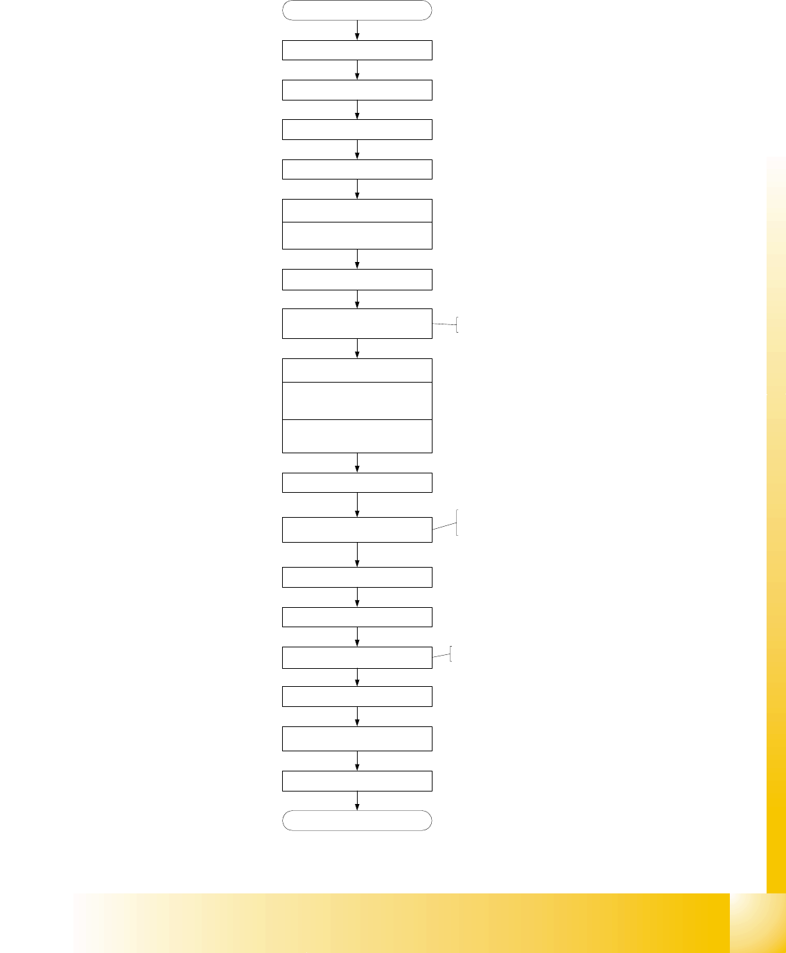
6.4.9 Determination of Zero Point Correction Star-Axis C&P Head
Fig. 6.4 - 18 Flow chart zero point correction
Menue C&P Heads
Select referring C&P Head
Menue Axes
Select Star axis
Positions
Zero point correction (ZPC) = 0
edit and accept
Axis reference run
disable Star / Z* Axis at axis
controller
Remove sleeve from segment 1
Turn segment 1 to bottom position
Mount Star axis Zero point gauge,
Insert fixing pin into gauge
DLM2 lower Z-Axis, that fixing pin
engage at segment
Select DP- and Star-Axis again
Enter actual position as new
Zero point correction (ZPC)
*
Remove Star zero point gauge
Insert sleeve
Enable Star (Z*) Servo
Execute Axis reference run
check position of the new Zero point-
correction (Segment 1 down)
Save machine data
End
start SITEST
* for DLM2 at HF-Machine:
* ZPC for HF-Machine: divide
actual Position by 2.5
* for DLM2 at HF-Machine:
1 - 70
Student Guide SIPLACE HF/HF3
6 Collect &Place-Head / DLM2 Edition 09/2005
70
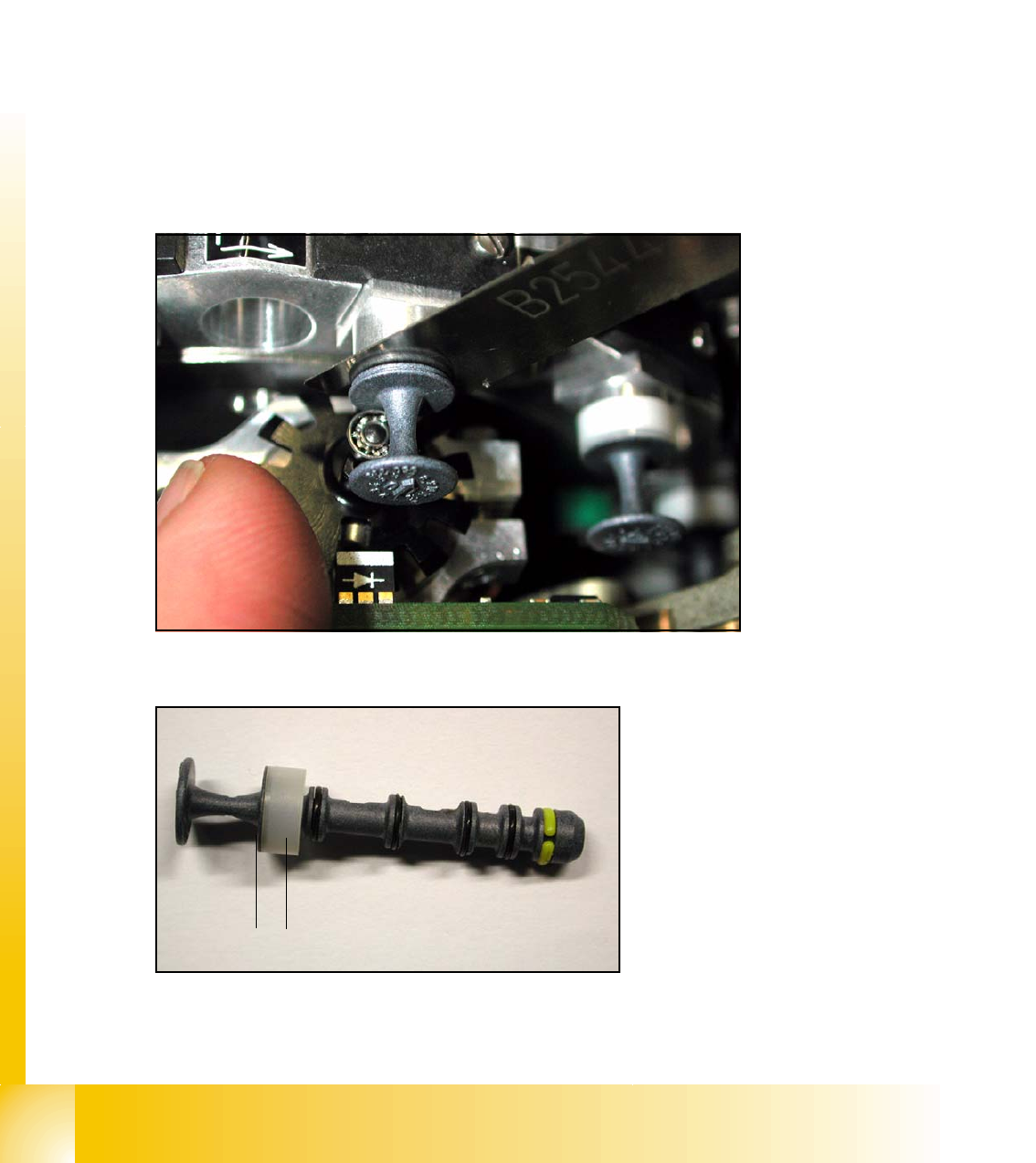
6.4.10 Adjustment of mechanical Position of Valve Drives
➠ If the new valve plungers are used (s. Fig. 6.4 - 20), proceed as follows:
– Take out one valve plunger and remove the plastic bushing
(2).
– Insert the plunger without bushing and carry out the following steps on this segment:
➠ Set the motor position of the valve drives "Pick-up / Placement" and "Ejection" according to the
figure below.
➠ Insert the distance gauge (0.2 mm) between valve plunger and valve casing.
➠ Turn the valve drive to 90° degrees, opposite to its initial position. The excentric of the valve
drive will just touch the inner flange of the valve.
➠ Fix the motor of the valve drive in this position.
➠ Don’t forget to refit the plastic bushing on the plunger.
6
Fig. 6.4 - 19 Mechanical position of the valve drive
6
Fig. 6.4 - 20 New Valve plunger, item.no:00351498-03
2
1