SG_FSE_SiplaceHF_HF3_00193901-05_eng.pdf - 第277页
1 - 77 S tudent Guide SIPLACE HF/HF3 Edition 09/2005 6 Colle ct &Place-Head / DLM2 77 6.5.3 Control nozzle changer on the C&P heads The nozzle changer are contr olled via CAN Bus. Depending on the location at the…
1 - 76
Student Guide SIPLACE HF/HF3
6 Collect &Place-Head / DLM2 Edition 09/2005
76
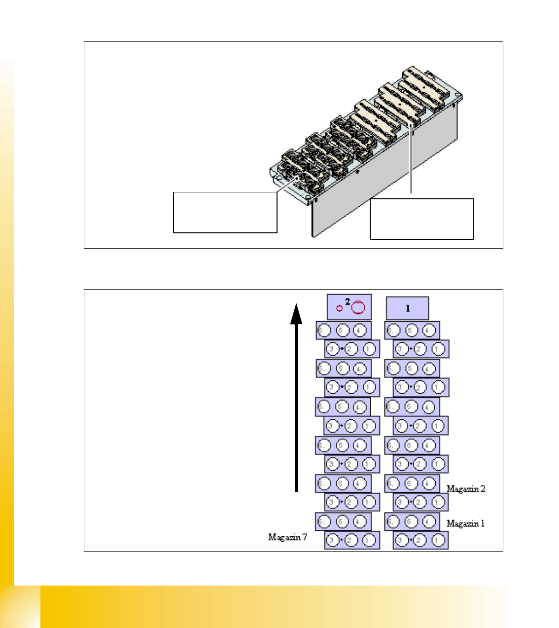
6.5.2 Nozzle changer for 6 segment C&P head
The nozzle changer for a 6 segment C&P head consists of at least one, and up to twelve maga-
zines, each with six nozzle garages (see Fig. 6.5 - 2). The magazines are seated on a common
support and each magazine is centered using two parallel pins and fixed in place with a spring
hook.
Magazines for the 9xx and 8xx nozzle types can be set up. The magazine types can be arranged
as required.
Fig. 6.5 - 2 Nozzle changer 6 segment C&P head
Fig. 6.5 - 3 Description of the positions nozzle changer
Magazin for 6
nozzle Typ 8xx
Magazin for 6
nozzle Typ 9xx
Transport direction
(1) Component reject position
(2) Nozzle reject position
1 - 77
Student Guide SIPLACE HF/HF3
Edition 09/2005 6 Collect &Place-Head / DLM2
77
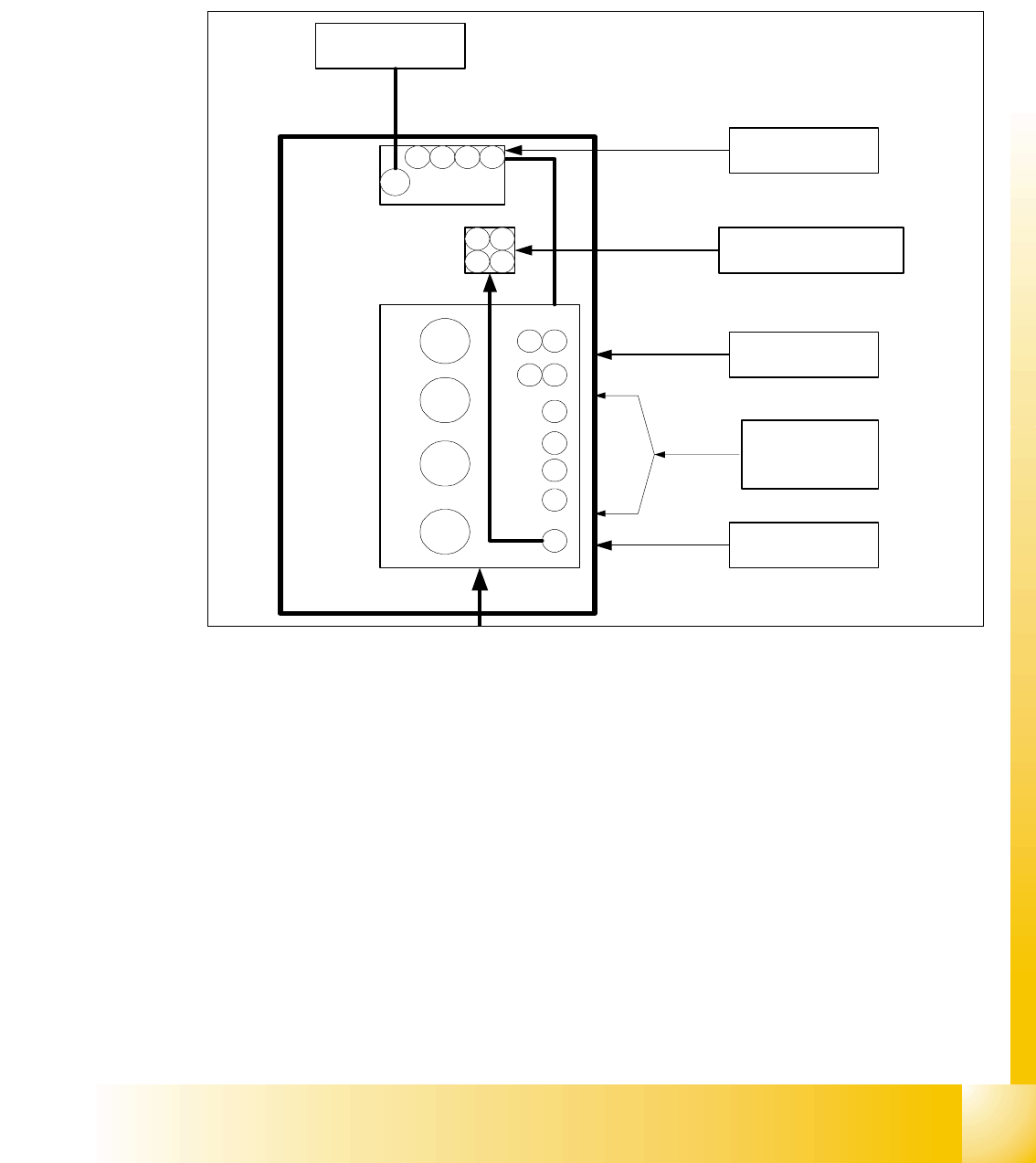
6.5.3 Control nozzle changer on the C&P heads
The nozzle changer are controlled via CAN Bus. Depending on the location at the machine the
SLIO at Main- or Sub-Distributor is used. At HF-machine version ’A’ the nozzle changer is control-
led via the "One Wire Bus". Solenoid valves activate the pneumatic rotary drives to open or close
the nozzle changer.
Fig. 6.5 - 4 Pressure air supply for the nozzle changer
3
4
2
1
Gantry 1 - 4
4
3
2
1
Bulkcase
Feeder
COT 1-4
2,5 bar
adjustable
Nozzle
changer
1 2
34
Nozzle changer
Gantry 1 - 4
2,5 bar
adjustable
Docking unit
1 - 4
5 bar
adjustable
Conveyor
5 bar
adjustable
5 bar
adjustable
1 2 3 4
Tape cutter
1 - 4
4 3
21