SG_FSE_SiplaceHF_HF3_00193901-05_eng.pdf - 第301页
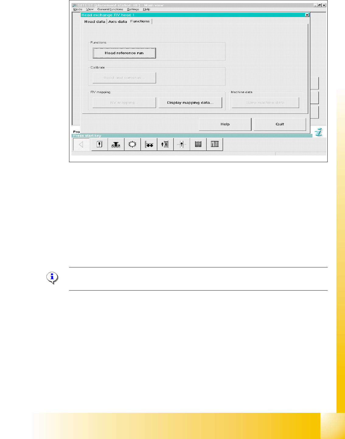
1 - 101 S tudent Guide SIPLACE HF/HF3 Edition 09/2005 6 Colle ct &Place-Head / DLM2 101 Fig. 6.7 - 7 Menu "Head exchange" --> "Functions (1) Head refere nce run to chec k the function and for calibr…
1 - 100
Student Guide SIPLACE HF/HF3
6 Collect &Place-Head / DLM2 Edition 09/2005
100
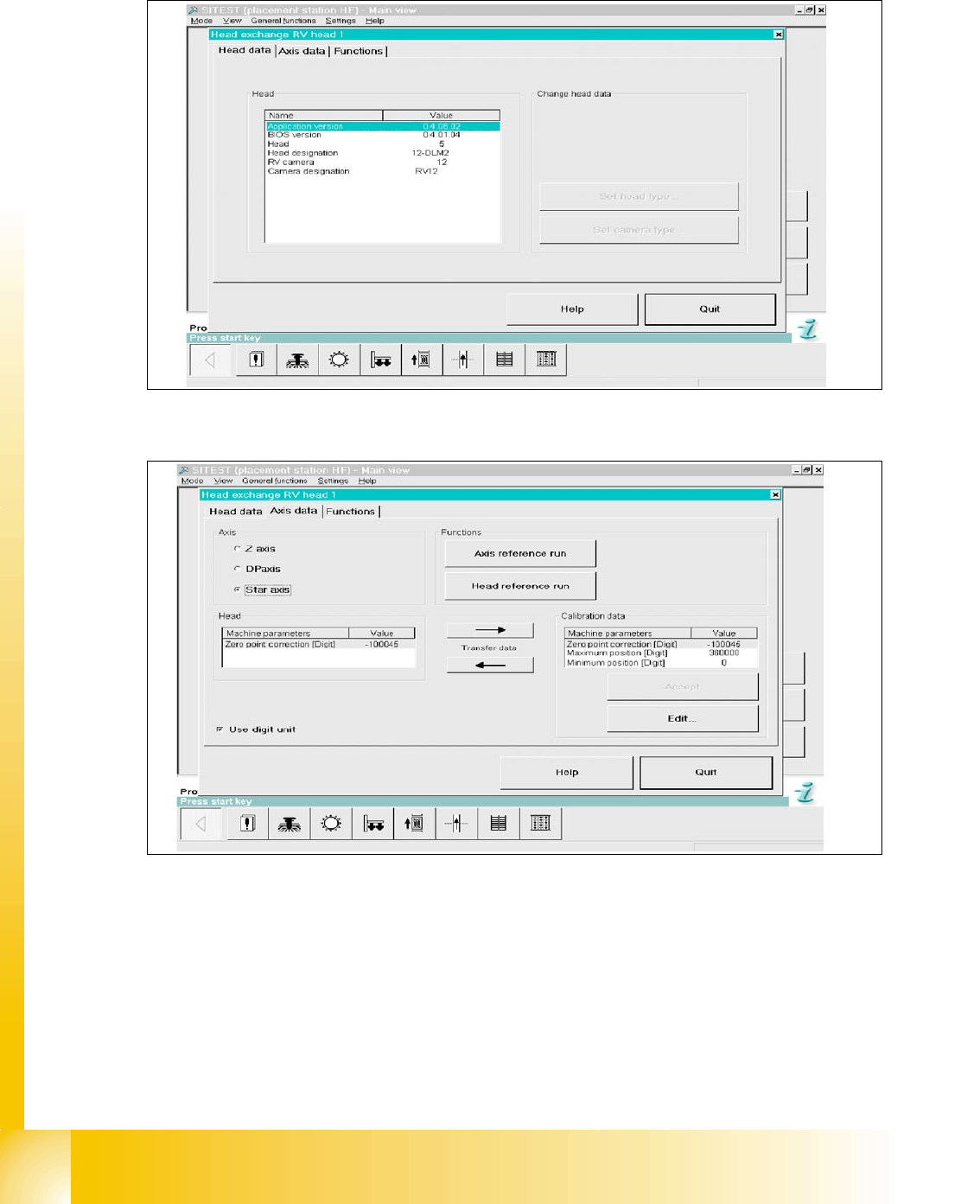
6.7.5 Menu Head exchange
Fig. 6.7 - 5 Menu "Head exchange" --> "Head data"
Fig. 6.7 - 6 Menu "Head exchange" --> "Axis data
(1) Read data from “head memory” write to RAM.
(2) Read data from RAM (MA data file) and write to “head memory”.
(3) Data taken from selected axis at RAM
(4) Data taken from selected axis at RAM (open to edit).
(5) Select head axis
(6) Link to this menu in placement head, axis reference run and head reference run.
1
6
5
4
3
2
1 - 101
Student Guide SIPLACE HF/HF3
Edition 09/2005 6 Collect &Place-Head / DLM2
101
Fig. 6.7 - 7 Menu "Head exchange" --> "Functions
(1) Head reference run to check the function and for calibration reference run the whole machine.
(2) Link to calibrate head and cameras.
(3) Mapping menu
(4) Display mapping data
(5) Link to machine data
6.7.6 Calibration
Please Note:
See Chapter Sitest "Calibration".
HF / HF3 C&P 6
➠ Calibrate zero point correction both gantries.
➠ Calibrate PCB camera
➠ Calibrate C&P head
➠ Component camera
➠ Segment offset 2
➠ Segment offset 1
➠ Calibrate nozzlechanger (inclusive automatic pick up height)
4
1
2
3
5
1 - 102
Student Guide SIPLACE HF/HF3
6 Collect &Place-Head / DLM2 Edition 09/2005
102
6.7.7 Head modularity C&P Head to Twin Head
6.7.8 Head modularity Twin Head to C&P Head
1. Data backup(see 8.5.3).
2. Remove C&P head with head
adapter.
3. Remove nozzle changer for C&P
head.
4. Mount stationary IC and/or FC-
camera.
Note: Twin head not possible in
placement areas with two gantries.
5. Mount Twin head with head
adapter.
6. Mount nozzle changer Twin
head at location 1.
7. Calibrate Twin head and
cameras.
8. With increase placement
accuracy carring out the fine
calibrationen.
Note: Check the DIP -Switches.
Change the grub screws into the
correct position.
1. Data backup(see 8.5.3).
2. Remove Twin head with head
adapter.
3. Remove nozzle changer for Twin
head.
4. Remove the stationary IC and/or
FC- camera.
Note: Remove the camera
"HEADCRASH".
5. Mount C&P head with head
adapter.
6. Mount the nozzle changer C&P
head at location 1.
7. Calibrate C&P head and
cameras.
8. With increase placement
accuracy carring out the fine
calibrationen.
Note: Check the DIP -Switches.