SG_FSE_SiplaceHF_HF3_00193901-05_eng.pdf - 第308页
1 - 108 S tudent Guide SIPLACE HF/HF3 6 Collect &Place-He ad / DLM2 Edition 09/2005 108 6.8.5.3 V acuum distributor disk st ar At the DLM 2 C&P head the vacuum d istributor disk for the ho lding and placemen t ci…
1 - 107
Student Guide SIPLACE HF/HF3
Edition 09/2005 6 Collect &Place-Head / DLM2
107
6.8.5 Changed parts of the DLM2 C&P head
6.8.5.1 Star brake
Due to the increasement of star acceleration and star decelaration a new optimized star brake
was required which stabalizes the star dynamics in the DLM head.
6
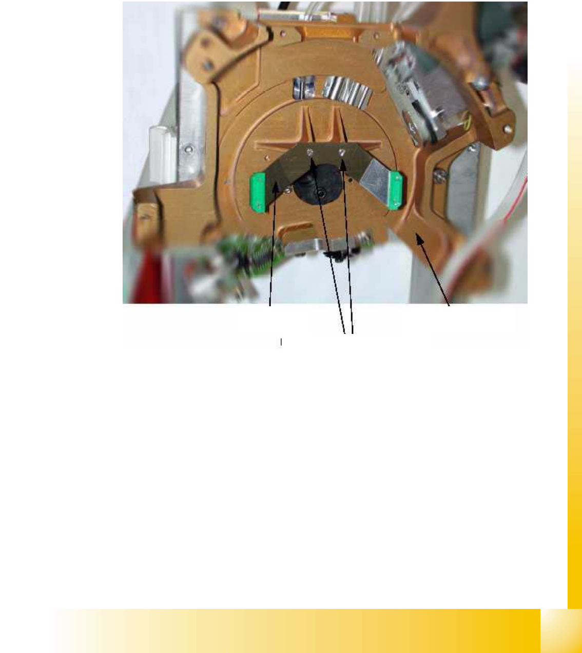
Fig. 6 - 2 Star brake
Rear part of the placement head
M1.6 x 4 mounting screw
Star brake
1 - 108
Student Guide SIPLACE HF/HF3
6 Collect &Place-Head / DLM2 Edition 09/2005
108
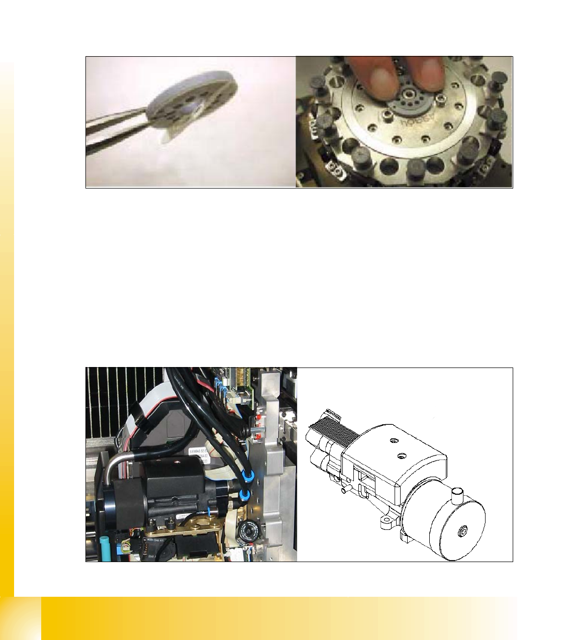
6.8.5.3 Vacuum distributor disk star
At the DLM 2 C&P head the vacuum distributor disk for the holding and placement circuit is glued
to the star assembly. By application of the new vacuum distributor disk the leakiness between star
assembly and distributor disk is eliminated as well as squeaking noises.
The gluing of the distributor disk ensures the clean sealing of the vacuum system.
Fig. 6.8 - 3 Mounting of distributor disk
6.8.5.4 Vacuum distributor / silencer
The adaptation of the new vacuum generator allows the application of the DLM 2 C&P head on
the machines HS-60, S 27HM and SIPLACE HF. The compressed air supply is made by a distri-
butor block fixed below the head PCB. From this distributor block two pneumatic hoses run to the
inlet
(2) of the vacuum generator. The exhausting air is guided through a silencer and parially
through a hose connected to the silencer
(1). The hose runs underneath the head PCB to the dis-
tributor block where the exhausting air emits to the environs. On the SIPLACE HF the exhausting
air is used for cooling linear motor of the X-axis.
Fig. 6.8 - 4 Vacuum generator
Order No. 12-nozzle C&P head: 00368211S01
Order No. 6-nozzle C&P head: 00368123S01
1
2
12
1 - 109
Student Guide SIPLACE HF/HF3
Edition 09/2005 6 Collect &Place-Head / DLM2
109
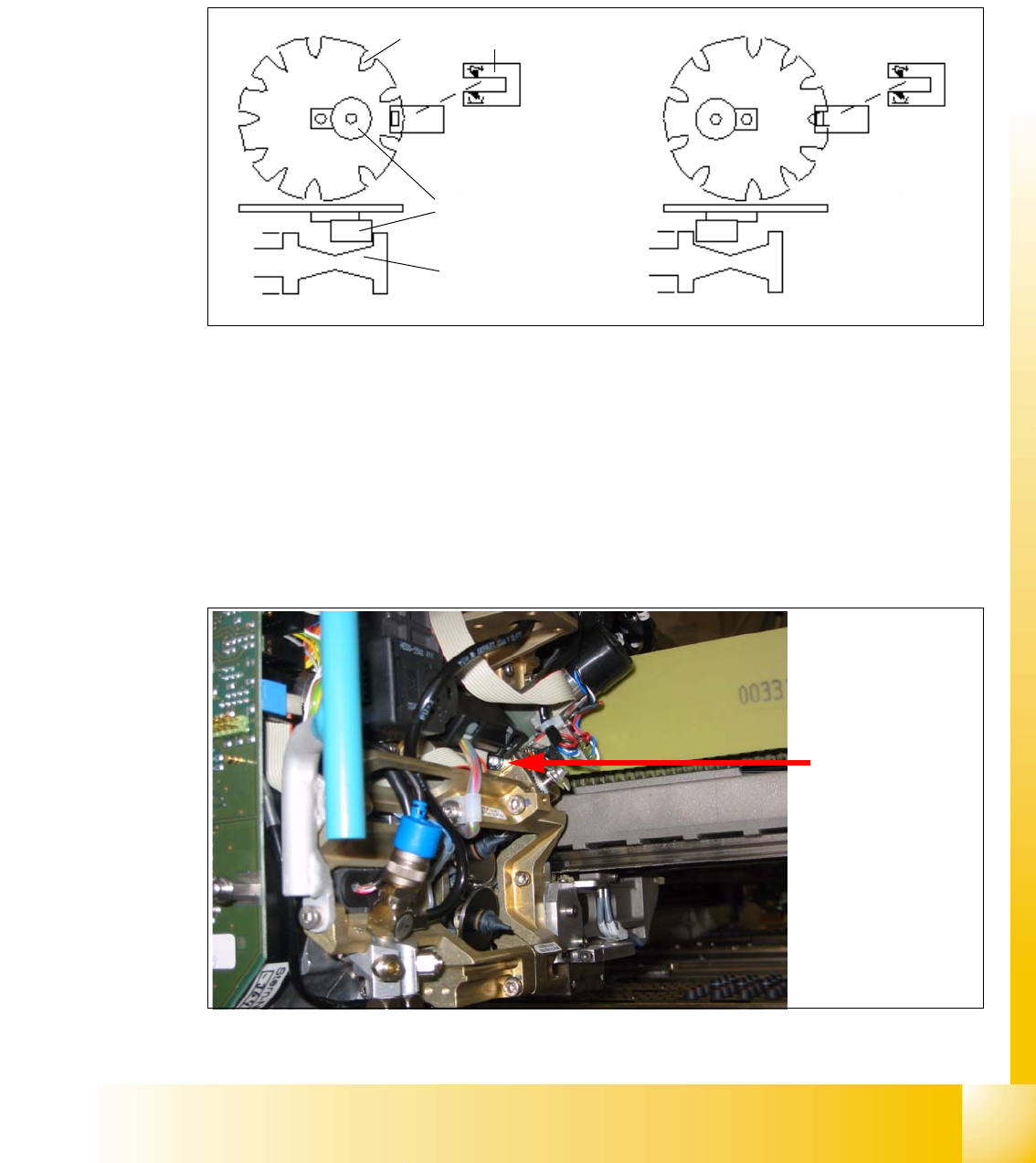
6.8.5.5 Encoder disk of the valve drives
The encoder disk (1) of the valve drives show additional slots (3) which allow a smoother position-
ing of the plungers
(5). Due to the additional slots resp. the increased angle resolution it is possible
to control the speed and to prevent bouncing of the plungers. Fig. 6.8 - 5 shows a valve drive with
excenter
(2) and fork light barrier (4).
Fig. 6.8 - 5 Top and side view of the encoder disk of the valve drive
6.8.5.6 Turning station ’DP-station’
The turning station of DLM 2 head and DLM 1 head have the same order no. The mounting of the
DLM 2 head is now fixed from the front with a M4 screw. The belonging thread is situated in the
turning station.
On the DLM 1 head the turning station was fixed from the back with a M3 screw through the M4
thread on the front part of the head.
Fig. 6.8 - 6 Mounting turning station
4
TOP VIEW
SIDE VIEW
3
2
1
5
fixing screw (M4)
turning station